2
\$\begingroup\$

I'm deveoloping a project with a raspberry Pi that involves serial communication. In order to properly handle voltage levels, I used a max3232 converter between the raspberry and the external device connectors.

Max3232 has two transmit lines and two receive lines. A pair of them is used by Tx and Rx (transfer and read the data buffer), whereas the other pair are labeled by default as the RTS/CTS flow control lines, as you can see in the picture.
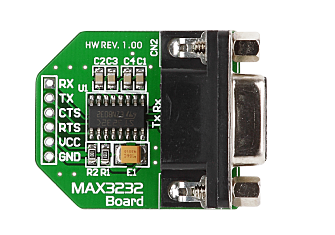
Max3232 board

My problem is related with this second pair: I would need a DTR line instead of the RTS. My first thought was to simply connect the RTS line to the DTR pin on the external device.

Is this idea valid?. Flow control pins are just the same with different names or are they governed by different schemes?

\$\endgroup\$
1
  • 1
    \$\begingroup\$ If you are using custom software this should be fine; if you want full flexibility you might switch the signal controlling the line in the kernel driver (implicit here is an assumption that the signal is under software control, and not a feature actually hardware linked to the state of the UART engine) \$\endgroup\$ Commented Apr 1, 2014 at 3:04

1 Answer 1

3
\$\begingroup\$

All RS232 pins are electrically identical. The MAX3232 device does level conversion on two pairs of lines but it can handle any of the lines.

The one thing to be careful about with the board shown is that if you switch lines on the logic-level (solder pad) side, you will end up with the signal on thw wrong pin of the DB9. You will need to modify the device on the other end of the cable or modify the cable.

\$\endgroup\$

Your Answer

By clicking “Post Your Answer”, you agree to our terms of service and acknowledge you have read our privacy policy.

Not the answer you're looking for? Browse other questions tagged or ask your own question.