7
\$\begingroup\$

I have been having a really hard time understanding the difference between blocking and non-blocking assignments in Verilog. I mean, I understand the conceptual difference between the two, but I am really lost when it comes to implementation.

I referred to a number of sources, including this question, but all the explanations seem to explain the difference in terms of code (what happens to the sequence of execution of lines when using blocking vs non-blocking). My question is a little different.

While writing verilog code (since I am writing it to be synthesized on an FPGA), I always try to visualize what the synthesized circuit is going to look like, and that is where the problem begins :

1) I am not able to understand how the changing from blocking to non-blocking assignments would alter my synthesized circuit. For example :

    always @* begin

        number_of_incoming_data_bytes_next <= number_of_incoming_data_bytes_reg;
        generate_input_fifo_push_pulse_next <= generate_input_fifo_push_pulse;

        if(state_reg == idle) begin
            // mealey outputs
            count_next = 8'b0;

            if((rx_done_tick) && (rx_data_out == START_BYTE)) begin
                state_next = read_incoming_data_length;
                end else begin
                    state_next = idle;
                end

        end else if(state_reg == read_incoming_data_length) begin
            // mealey outputs
            count_next = 8'b0;

            if(rx_done_tick) begin
                number_of_incoming_data_bytes_reg <= rx_data_out;
                state_next = reading;
            end else begin
                state_next = read_incoming_data_length;
            end

        end else if(state_reg == reading) begin

            if(count_reg == number_of_incoming_data_bytes_reg) begin
                state_next = idle;
                // do something to indicate that all the reading is done
                // and to send all the data in the fifo
            end else begin
                if(rx_done_tick) begin
                    generate_input_fifo_push_pulse_next = ~ generate_input_fifo_push_pulse;
                    count_next = count_reg + 1;
                end else begin
                    count_next = count_reg;
                end
            end

        end else begin
            count_next = 8'b0;
            state_next = idle;
        end
    end

In the above code, how would the synthesized circuit change if I replaced all the blocking assignments by non-blocking

2) Understanding the difference between blocking and non-blocking statements when written sequentially is a bit simpler (and most answers to this question focus on this part), but how do blocking assignments affect behaviours when they are declared in separate conditional behaviours. For example :

Would it make a difference if I wrote this:

if(rx_done_tick) begin
    a = 10;
end else begin
    a = 8;
end

or if I wrote this :

if(rx_done_tick) begin
    a <= 10;
end else begin
    a <= 8;
end

I know that conditional statements synthesize to become multiplexers or priority structures, and so I feel that using either blocking or non-blocking statements should not make a difference, but I am not sure.

3) When writing testbenches, I the result of the simulation is very different when using blocking v/s non-blocking statements. The behaviour is very different if I write :

initial begin
    #31 rx_data_out = 255;
    rx_done_tick = 1;
    #2 rx_done_tick = 0;
    #30 rx_data_out = 3;
    rx_done_tick = 1;
    #2 rx_done_tick = 0;
    #30 rx_data_out = 10;
    rx_done_tick = 1;
    #2 rx_done_tick = 0;
end

versus when I write this :

initial begin
    #31 rx_data_out <= 255;
    rx_done_tick <= 1;
    #2 rx_done_tick <= 0;
    #30 rx_data_out <= 3;
    rx_done_tick <= 1;
    #2 rx_done_tick <= 0;
    #30 rx_data_out <= 10;
    rx_done_tick <= 1;
    #2 rx_done_tick <= 0;
end

This is very confusing. In my practice, the rx_done_tick signal is going to be generated by a Flip Flop. So, I think that non-blocking statements should be used to represent this behaviour. Am I right ?

4) Finally, when to use blocking assignments and when not to use non-blocking statements ? I.e is it true that blocking statements should be used only in combinational behaviours , and non-blocking statements in sequential behaviours only? If yes or No, why ?

\$\endgroup\$
2
  • 2
    \$\begingroup\$ Not having this dilemma is one of the biggest advantages of VHDL. \$\endgroup\$
    – user16324
    Commented Mar 15, 2016 at 16:14
  • \$\begingroup\$ It's not really a dilemma. I didn't use blocking statements for the first ~3 years of coding verilog. You just don't use them. \$\endgroup\$
    – stanri
    Commented Jan 21, 2019 at 17:35

6 Answers 6

4
\$\begingroup\$

The blocking vs non blocking assignment is a crucial concept and you have difficulty to implement them correctly because you have not understood the conceptual difference.

I have attached a slide of MIT OCV PowerPoint lecture, 2005, that clearly describe the difference between the two

Blocking vs non blocking assignment

You must understand the concept of RHL (Right Hand Side) calculation. Verilog always calculates the RHS and puts it into LHS. In blocking, the assignment happens exactly after the calculation is done, while in non-blocking, the assignment of RHS to LHS happens when the end of block is reached. That is why as 'the Photon' has mentioned for single lines both blocking and non-blocking will be the same but if you have more than one lines then things MIGHT change or might not change!

\$\endgroup\$
2
4
\$\begingroup\$

1) I am not able to understand how the changing from blocking to non-blocking

The example code posted was for a combinatorial block, changing all blocking (=) to non-blocking (<=) may affect simulation but will not affect synthesis. This results in a RTL to gate level mismatch. It is an incorrect place to use the non-blocking assignment, do not use it in a combinatorial section.

To summarise for the other question non-blocking simulates that data changing just after an event such as the posedge of a clock. This allows correct simulation of a flip-flop.

this implies for testbenches:

initial begin
    #31 rx_data_out = 255;

At time 31 the assignment happens.

initial begin
    #31 rx_data_out <= 255;

Just after time 31 the assignment happens. Try both in parallel with a

initial begin
  #31 $display(rx_data_out);
end 

For the first example you actually have a race condition both happen at the same time, you should get 255 printed out. For the second example you will always have x printed because the assignment happens just after the time 31 event, not on it.

non blocking can be useful for testbenches were you want to mimic data being driven by flip-flops, i.e. it changes just after the event. for example releasing a power on reset.

initial begin
  @(posedge clk);
  @(posedge clk);
  rst_n <= 1'b0;
end

Imagine we had a series of flip-flops (a,b,c) creating a delay line, they each have d input and q output.

if the assignments were chained with :

c = b = a

Data would rush through from a to c instantly. but if we have

c <= b <= a

we have a pipeline, and each flip-flop can hold its value.

Actual code:

always @(posedge clk) begin
  c = b;
  b = a;
  a = in;
end

versus:

always @(posedge clk) begin
  c <= b;
  b <= a;
  a <= in;
end

This is why for question 2 with only one assignment it does not matter. but if there are multiple assignments that rely on each other it really does matter because you're controlling if it is driven from a flip-flop (<=) or a block of combinatorial logic (=).

My rules of thumb: Use blocking (=) for combinatorial logic and non-blocking (<=) for sequential (flip-flops)

\$\endgroup\$
0
1
\$\begingroup\$

Question 1

is too big to answer here. If you really want to know, write it both ways and simulate

Question 2

If you only have one statement in a procedural block, it doesn't matter (at least practically) if it's blocking or non-blocking.

Question 3

Your testbench isn't going to be implemented in flip-flops, it's only going to be interpreted by the simulation tool. Don't worry about how testbench code will synthesize.

Question 4

I learned to always use non-blocking for synthesis code. Use blocking only for special cases where it makes code easier to understand. But there are other philosophies on this.

\$\endgroup\$
2
  • 1
    \$\begingroup\$ #3 my testbench containg rx_done_tick as a signal right now, but it is will later be an output signal from the uart module. So, it is going to be synthesized. \$\endgroup\$
    – ironstein
    Commented Mar 15, 2016 at 16:16
  • 2
    \$\begingroup\$ @ironstein, then you need to get rid of all those delay elements (#31, etc), as they are not synthesizable. To write for synthesis, provide a clock, build a state machine, and drive the output signals according to the FSM state. \$\endgroup\$
    – The Photon
    Commented Mar 15, 2016 at 16:21
1
\$\begingroup\$

This is more of an addendum to pre_randomize's answer, but as comments do not allow for images I am posting as an answer.

The general rule of thumb, as already stated is:

Use blocking (=) for combinatorial logic and non-blocking (<=) for sequential (flip-flops)

The D flip-flop chain is a good example of how using the wrong assignment (in this case a blocking assignment for sequential procedures) creates simulation results inconsistent with synthesized logic.

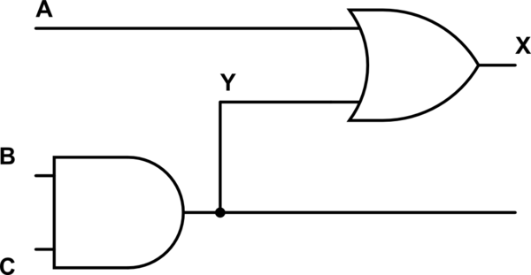
The flip side is if you have multi-level combinational logic, as shown below:

schematic

simulate this circuit – Schematic created using CircuitLab

In this case, if we were to write this as two separate lines for outputs X and Y, we would write:

Y = B&C;
X = A^Y;

Which makes sense, Y is first becomes B*C and after that, X becomes A+Y. Note that there is implicit ordering because of the way the gates are drawn, the AND gate resolves before the OR gate because a wire goes from the AND gate to the OR gate.

Consider what you are describing if you write the following:

Y <= B&C;
X <= A^Y;

In this case, we are saying Y becomes B*C simultaneously with X becoming X+Y (within the same time-step). This means that a simulator will evaluate Y with the previous (last time-step) values of B and C (not a problem) but also X with the previous values of A and Y (potentially incorrect).

\$\endgroup\$
1
\$\begingroup\$

A very simple answer might solve the problem. When you are performing synthesis, you are using a sub-set of the full expressive capabilities of the verilog language. In synthesised logic, you can have flops, latches and combinatorial logic. Flops and latches in particular are infered by the synthesis tool using templates.

If you write a clocked function with a blocking assignment, simulation is happy, but it won't match your FPGA behaviour. For compatibility or legacy reasons, the synthesis tool might not refuse to accept the input, and will just complain. Simply, never try this.

The only time you will see a simulation expose these different behaviours for a clocked function in otherwise synthesisable code is where the RHS of an expression is updated by other clocked blocks. I visualise this as being similar to setup-hold problems, which look equally strange if you draw timing diagrams for a zero-delay simulation. In practice, flop outputs always change after the clock edge, but looking in simulation this information is usually not shown.

\$\endgroup\$
0
\$\begingroup\$

I have found a satisfactory answer and need input for it. I feel we should use Nonblocking statements for both combinational and sequential statements.

For sequential it is pretty clear y we should use.

I will describe the reason for Combi Blocks.

For eg. take the following code

module block_nonblock(output logic x,x1,y,y1,input logic a,b,c);

always@* begin : BLOCKING
    x1 = a & b;
    x  = x1 & c; 
end

always@* begin : NONBLOCKING
    y1 <= a & b;
    y  <= y1 & c; 
end

endmodule

Here the same hardware is inferred for both the circuits.

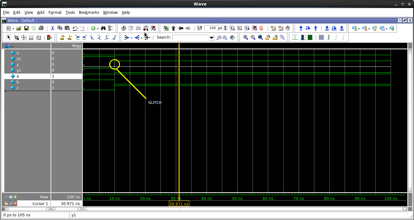
Simulation waveform depicting glitch

However, if we give the inputs together as (A = 1,B = 1,C = 0) and then change them together after say 10ns as (A=1,B=0,C=1) then we can see that there is a glitch. This glitch will be there in actual Hardware as well. But this is only shown in simulation by Nonblocking Statements Output (Y) and not by Blocking Statements Output (X).Once we see a glitch we van take additional measures to prevent this from happening, so that it doesnt happen in hardware.

For combinational segments we will use Nonblocking Statements because, when we use Blocking or NonBlocking statements, even though it gives us the same hardware or RTL in the end; it is the nonblocking statements which shows us the glitches in simulation. Theses glitches will be there in hardware as well (because of Gate Delays), so we can rectify them when we see them in Simulation so that they will cause less harm at a later stage of the design/development cycle.

Hence i feel it is safe to conclude that we must use Nonblocking statements for combi blocks.

\$\endgroup\$
2
  • \$\begingroup\$ When you use nonblocking statements for combinational blocks, the output you observe in simulation will be wildly different what you would observe from the synthesized circuit. It is true that both the circuits synthesize to be the exactly same, but the presynthesis simulation and postsynthesis simulation would differ (basically you are just simulating the wrong circuit, and synthesizing the right one. Does not mean that the output will be the one you saw in simulation). Basically, you are designing the entire circuit wrong (because you are simulating it wrong). \$\endgroup\$
    – ironstein
    Commented Apr 7, 2016 at 18:17
  • \$\begingroup\$ Hi @ironstein , could you you elaborate with respect to the above circuit. I didn't understand y you termed it as wrong. My intention is to make a 3-input AND gate using 2-i/p AND Gates., and decide which statement(Blocking or Nonblocking) would be best. Isn't the above circuit doing the same thing(3 i/p AND Gate). How is the circuit wrong..? What am i missing here...? \$\endgroup\$ Commented Apr 11, 2016 at 6:42

Your Answer

By clicking “Post Your Answer”, you agree to our terms of service and acknowledge you have read our privacy policy.

Not the answer you're looking for? Browse other questions tagged or ask your own question.