10
\$\begingroup\$

I was given a small task (actually it's part of a much larger task) where the requirement is to generate a signal which looks like it came from a microphone. The following requirements needs to be kept:

  • 1.0Vpp
  • Sine Wave
  • Differential

Now these are actually two questions:

  • I understand that the signal needs to be differential, so I need two signals but must these two be symmetrical around 0V? What is the normal output a microphone gives here. Otherwise: Could I just use a single sine wave, multiply it by two and the input to the receiver would look the same?

  • What is a cheap way I could do this? I understand that I could use a microcontroller and its DAC feature to generate a nice sine wave. Yet, how would I get a differential signal from that. Or is there any IC which already does what I want?

\$\endgroup\$
5
  • \$\begingroup\$ You might want to note what kind of microphone you're simulating. It depends on what microphone you're imitating what kind of signal there would be. \$\endgroup\$
    – user17592
    Commented Jan 13, 2013 at 13:13
  • 1
    \$\begingroup\$ That's one heck of a microphone if it's putting out 1 Vpp! Almost certainly it is a preamp output you have been asked to emulate. The microphone part is irrelevant, whether the preamp is built into a microphone or is elsewhere. \$\endgroup\$ Commented Jan 13, 2013 at 13:59
  • \$\begingroup\$ It's called a hint :-) \$\endgroup\$
    – user17592
    Commented Jan 13, 2013 at 14:26
  • \$\begingroup\$ @OlinLathrop: I can get 1 Vpp on some drum microphones, easy. \$\endgroup\$
    – Phil Frost
    Commented Jan 13, 2013 at 14:41
  • 3
    \$\begingroup\$ @OlinLathrop A contact piezo pick-up microphone as used with various percussion musical instruments will routinely deliver voltages so high (10 Volts and more) that input clamping is often needed at the 10s of Volts. \$\endgroup\$ Commented Jan 13, 2013 at 15:03

6 Answers 6

9
\$\begingroup\$

I would approach this as two problems, generating a sine wave, and making a balanced line driver. Other answers have covered the sine wave generator, and it's an easy thing to research, and I have nothing to add there. However, I'll say some things about the differential line driver.

As some others have said, the canonical way to do this is with a transformer. Transformers work great, but are big and expensive. In audio applications you will need an even more expensive transformer to avoid introducing unacceptable distortion. However, if you want to look exactly like a dynamic microphone, this is your best option, since a transformer simulates more of the properties of the windings on a dynamic microphone than any other method.

However, any balanced audio signal you get from any modern device that is powered probably won't have a transformer these days, because of cost. Powered (condenser) microphones may fall into this category; mixing boards and preamps almost certainly do. I highly recommend you read Design of High-Performance Balanced Audio Interfaces for a survey of common techniques and a detailed explanation of the relevant concerns. Also see Balanced Transmitter and Receiver II from the same site.

There's one part of that later article in particular I'll summarize here: What's important is that the impedance of both lines is the same, so that noise will result in the same voltage, so that it can be rejected as common-mode. Having an opposite signal on the negative side doesn't matter at all. In that article, there's a schematic, under the section Hey! That's cheating:

balanced line driver schematic

See the article for detailed discussion, but you can plainly see that pin 3, the negative side of the signal, is just a connection to ground through a resistor. As it turns out, if you disassemble a lot of professional audio equipment, this is precisely the type of line driver they use. It's because it has quite a few advantages:

  • Simple
  • Easy to balance
  • If pin 3 is connected to ground on an unbalanced input, nothing bad happens

The only critical part here is making sure R2 and R3 are exactly equal. Use 1% or better resistors, or balance them with a Wheatstone bridge for best common-mode rejection.

\$\endgroup\$
1
5
\$\begingroup\$

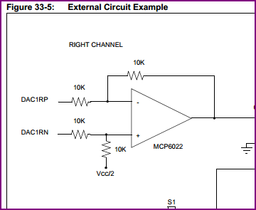
If I understand correctly, you want a circuit that generates the sine wave and also provides two versions of it 180 degrees apart. This could be easily achieved with a microcontroller, like a dsPIC with dual 16-bit DAC with differential outputs on each channel (such as the dsPICfJ64GP802 - here is the DAC peripheral manual for it), here is a typical differential buffer circuit driven from one of the channels:

dsPIC DAC Buffer


No Microcontroller

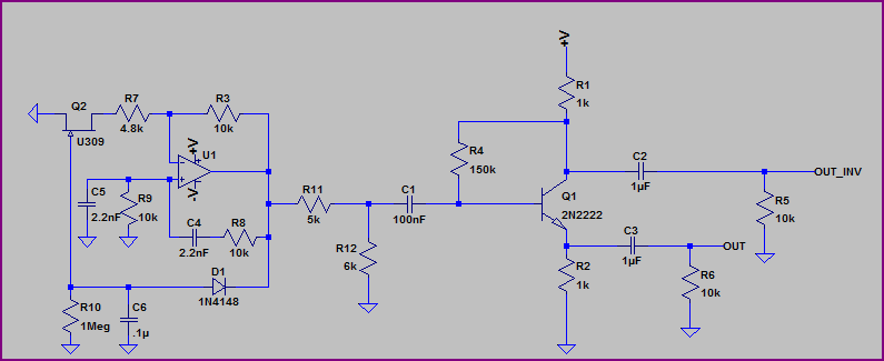
Here is a non-micro option:

Diff Output

This combines a Wien bridge oscillator (the fet can be replaced with an incandescent bulb if desired) with a simple transistor buffer which takes an output from the collector and emitter. Rails are +/- 12V (can be designed for lower if necessary)

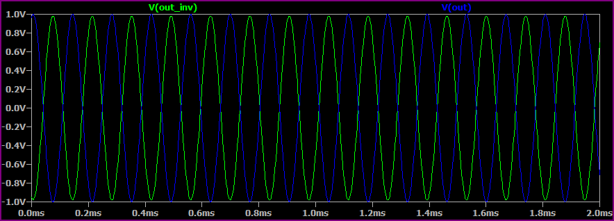
Simulation:

Diff Output Simulation

Note that the above will sum to 2V pk-pk when it get's to wherever it's going - you can easily control the amplitude by replacing R11 and R12 with a pot.

\$\endgroup\$
4
\$\begingroup\$

When you have an asymmetric signal and want a symmetric (read: differential) signal, and your required signal should look like it's from a (dynamic) microphone (except you want a higher level of 1 Vpkpk), the device of choice is a DI Box.

These contain, in their passive version, an audio-frequency transformer, and there's usually a center-tap on the output side that may be connected to GND with a switch if desired. Also, there are active versions, using OpAmps instead of a transformer. These use, simplified, a buffer and an inverter. The buffer creates the signal in-phase with your source, and the inverter creates the signal that is 180° out of phase compared to the original signal. Buffered and Inverted = Differential.

Usually, your differential signal is symmetric around 0 V. The output side of a transformer is even floating as long as you leave the switch open (i.e. symmetrical to nothing than its own mean value), which is an added benefit to avoid ground loops.

\$\endgroup\$
2
  • \$\begingroup\$ zebonaut, as far as I understand, wouldn't this be the other way round? Isn't a DI box meant to generate some "powerful" signal from a microphone signal? At Thomann.de I could find a various number of DI boxes, can you recommend one? thomann.de/de/diboxen_symmetrierboxen.html \$\endgroup\$
    – Tom L.
    Commented Jan 13, 2013 at 14:29
  • \$\begingroup\$ @TomL. DI boxes are used when you have a "line out" (e.g. from a keyboard or sampler or cd player) and want to run it through the hall to the main mixing console. Microphones (at least dynamic ones) usually are not preamplified on the stage, their signal can often be run all the way to the mixing desk without being amplified by any gadget. \$\endgroup\$
    – zebonaut
    Commented Jan 14, 2013 at 8:47
4
\$\begingroup\$

A transformer as zebonaut suggests will certainly produce a nice differential signal with a bonus of common mode isolation.

Another way is to produce two signals in the first place. Since you are synthesizing this, that shouldn't be hard to arrange. Use two D/As or filtered PWM outputs of a microcontroller, for example. You can guarantee the averag is always the same easily enough in firmware. These two signal would still have a DC offset of half the supply voltage, but that is common with audio circuits. You buffer the two signal, then couple them each thru a cap to the output. Put a weak resistor, like 10 kΩ to ground on each output to shift the average to ground and to leak off any static charge that might accumulate and let the voltage get too high for the caps to hold off.

Added about buffering

"Buffering" a voltage signal generally means to keep the voltage about the same but to significantly lower the impedance. Put another way, a buffered signal can source a lot more current than its unbuffered version.

A simple way to buffer a signal is with a opamp in "voltage follower" mode. This is just a opamp with its output tied back to its negative input. Whatever you then put on the positive input shows up on the output, but with the opamp's current drive capability.

In your case, the A/D or filtered PWM outputs will be high impedance and not suitable for sending over a cable. Two opamps configured as voltage followers will fix that.

\$\endgroup\$
2
  • \$\begingroup\$ Olin, thanks for this idea, I really like it very much since I have the opportunity of generating as many digital signals as i want without any additional hardware. Another question: What do you mean by buffering the generated analog signal. I understand the idea of taking out the DC part of the signal with the capacitors and then tying them to ground as a reference, but why would I need to buffer them (and how would I do that?) \$\endgroup\$
    – Tom L.
    Commented Jan 13, 2013 at 14:26
  • \$\begingroup\$ @Tom L: See addition to answer. \$\endgroup\$ Commented Jan 13, 2013 at 14:32
2
\$\begingroup\$

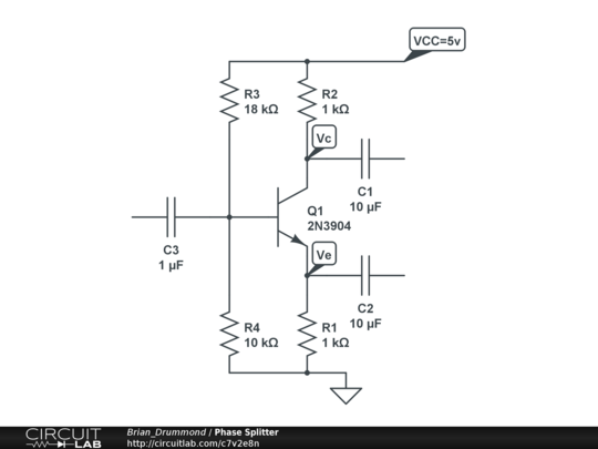
A simple phase splitter can be made from a single transistor with the same resistance in the collector (inverted) emitter (non-inverted) circuits. Its balance is pretty good but depends on the hFE of the transistor.

https://www.circuitlab.com/circuit/7v2e8n/phase-splitter/

Values should be close enough for 5V. Check that Ve is about Vcc/4 (which puts half the supply voltage across the transistor) and adjust R3 or R4 if necessary.

\$\endgroup\$
0
\$\begingroup\$

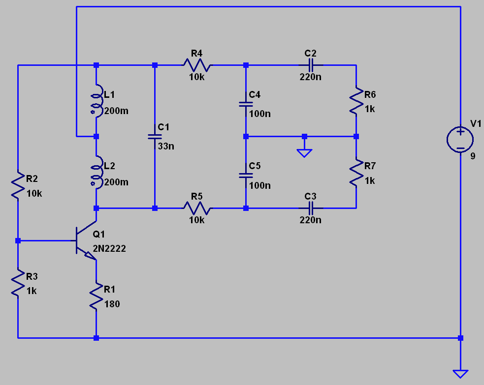
Old question but I thought I would add my 2 cents to the mix - How about a simple 1-transistor LC oscillator using the split primary of a small audio transformer? Such a solution would look something like this: lc audio osc schematic

outputs on R6 and R7

\$\endgroup\$

Your Answer

By clicking “Post Your Answer”, you agree to our terms of service and acknowledge you have read our privacy policy.

Not the answer you're looking for? Browse other questions tagged or ask your own question.