2
\$\begingroup\$

Let's say you've got a standard astable multivibrator (AMV) 555 circuit that includes all the wiring, two resistors (R1, R2) and a capacitor (C1). I wonder what is the purpose of the capacitor and how does it affect the frequency?

For some capacitors the frequency is not "clean" - it fluctuates and for some it's very stable, why is that so?

\$\endgroup\$

2 Answers 2

8
\$\begingroup\$

You should provide a link to the circuit diagram. The component names may vary.

Assume R1 is the charge resistor and R2 is the discharge resistor.

A capacitor is like a water reservoir. Current flows into it and it fills - but with charge rather than water. As the current flows in the "head" increases - in this case the measure of fullness is the capacitor voltage. So

Current flows into the capacitor via R1 and R2 in series. The voltage on the capacitor rises. The two resistors and the capacitor between them set how long it takes the capacitor to fill so they affect that part of the oscillator cycle.

At a certain voltage level the 555 "decides" there is enough voltage on the cap so it turns on a discharge transistor inside it. The capacitor now discharges via R2. The cap and R set the time taken for the discharge part of the oscillator cycle.

So the capacitor slows down the rate of rise and the rate of fall of voltage. Without the capacitor the circuit would try to oscillate very fast and would not be controllable or predictable.

With a capacitor the time to charge is ABOUT t= (R1+R2) x C.
The time to discharge is ABOUT t = R2 x C.

Looks for circuit - oh good, R names are the same as I used ;-)
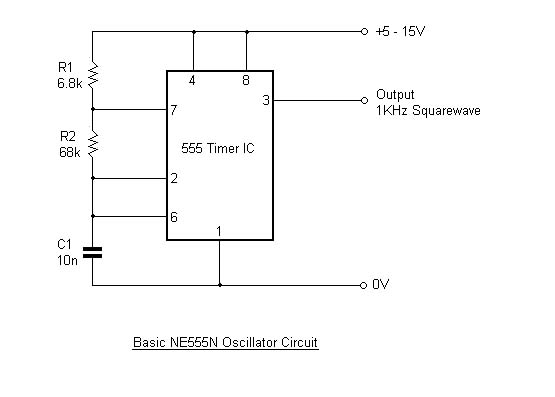
enter image description here

NE555 data sheet here


If undamaged and correct polarity caps are used the oscillation should be stable as long as the data sheet limits are met. It MAY be that some capacitor values are outside the allowable range.


"Charge flow"

While it may be stated with some justification that charge does not flow into a capacitor but rather that it flows from one "side" to the other, the statement is confusing as all get out for beginners and is not in fact strictly correct either. And in some cases is almost completely incorrect. Almost.

ie - the claim that capacitors do not fill with charge should only be made in pubs or closed meetings of the verbal pedants society OR decent references to the overall relevant material should be given.

It will confuse beginners immensely to make such statements in isolation.
Consider eg the classic V=q/C and how it is usually used and explained.
Consider mutual capacitance and the fact that an isolated sphere of Radius R has C=kR and that charge does indeed flow into it to charge it
. (The earth has a capacitance of about 700 microFarad).
And more.

An extremely good treatment is given by the Wikipedia Capacitance entry. Understand half of what's there and you are well on the way to starting to start to become a Grand Master [tm].

\$\endgroup\$
14
  • \$\begingroup\$ The voltage over the capacitor oscillates between 1/3 and 2/3 of the supply voltage (there's an internal voltage divider that feeds two comparators). \$\endgroup\$
    – starblue
    Commented Sep 26, 2011 at 16:15
  • \$\begingroup\$ @starblue - ? & yes. That's why I said that charge and discharge times are about the same as the time constants involved. ie the cap is swinging across a range of about 1/3 of supply so using t=RC is in the order of correct. \$\endgroup\$
    – Russell McMahon
    Commented Sep 26, 2011 at 16:44
  • \$\begingroup\$ Capacitors don't "fill with charge". A charged capacitor has the same net charge as an uncharged capacitor. \$\endgroup\$
    – endolith
    Commented Sep 26, 2011 at 17:18
  • 1
    \$\begingroup\$ endolith: So it would be wrong to say that a charged battery had a charge? Seriously?! \$\endgroup\$ Commented Sep 26, 2011 at 19:37
  • 1
    \$\begingroup\$ Sorry, that's just absolute nitpicky silliness. The capacitor fills with charge as each plate acquires a charge relative to the other one. The accumulated charge results in a growing electric field. \$\endgroup\$ Commented Sep 27, 2011 at 5:51
2
\$\begingroup\$

First note that it does not help to refer to R1, R2, C1, without reference a circuit. The standard 555 circuit has 2 capacitors, I guess you are refrerring to the one at pin 6. The other one (at pin 5) is for stability, it has nothing to do with the frequency.

If the datasheet does not say it all, this chip is so famous it has a wiki page all for itself! http://en.wikipedia.org/wiki/555_timer_IC states: In the astable mode, the frequency of the pulse stream depends on the values of R1, R2 and C. Cut-n-paste of the formula does not work, but you can check it here (or in the datasheet).

\$\endgroup\$
2
  • \$\begingroup\$ Thanks for the response - but you didn't answer what is it used for on the electrical level. I know it's used for the frequency setting - but how does it really effect the frequency and why it's unstable for some values? Thanks :) (and yes, it's the basic astable circuit without the optional capacitor) \$\endgroup\$
    – roman
    Commented Sep 26, 2011 at 18:08
  • \$\begingroup\$ fairchildsemi.com/ds/LM/LM555.pdf p6: the capacitor is charged through the two resistors. For a higher value capacitor, it will take longer for the voltage on the capacitor to reach the trigger level. \$\endgroup\$ Commented Sep 26, 2011 at 21:15

Your Answer

By clicking “Post Your Answer”, you agree to our terms of service and acknowledge you have read our privacy policy.

Not the answer you're looking for? Browse other questions tagged or ask your own question.