Is there any reason to cancel the inductive and capacitive reactance out for an antenna operating on 13.56 Mhz ? Why do we need to cancel the reactances out I followed a tutorial when designing a T-match antenna but I did not really understand the relationship between the antenna and the resoncance frequency. How will that affect the antenna?
2 Answers
Antennas at 13.56 MHz are usually used for near field communication. This is dominated by inductive coupling and, to make life easier on the "driving" transmitter electronics, a capacitor is added to make it electrically resonant. This helps the electronics produce a bigger magnetic field and additionally it acts like a filter so that spurious harmonics are substantially removed thus reducing EMI.
Making it resonant like this makes the antenna purely (or very nearly) resistive even when the remote RFID device is getting quite close.
If the antenna is in fact a regular EM antenna then the word "resonate" can take on a subtly different meaning. In this example resonating the antenna means matching its size so that it produces an electric field 377 times bigger than the magnetic field (hence Jim's comment). But what is this magical number you might ask - it's the impedance of free space governed by \$\epsilon_0\$ and \$\mu_0\$. These parameters define the speed of light in a vacuum and the speed of an EM wave but, their ratio defines the impedance of free space.
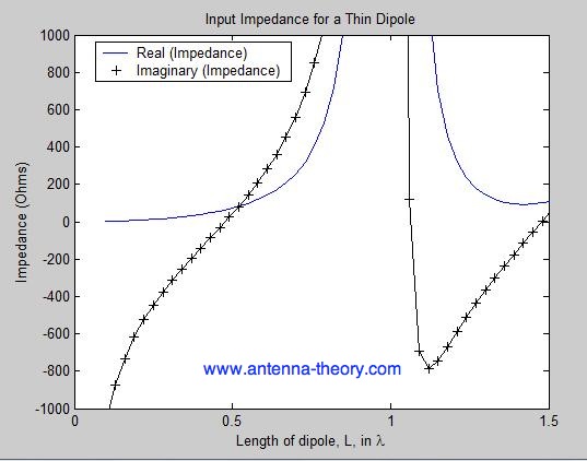
So, given that our antenna needs to emit individual E and H fields at the right ratio for maximizing transmission distance, we make the length of an antenna optimized for this. Having said this, it doesn't mean that electrically the antenna looks like a resistor: -
The above is for a dipole antenna and it is usually made to be half a wavelength long. Looking at it from an electrical standpoint yields an impedance of 73 + j43 Ohms. In other words it can be electrically optimized by cancelling the imaginery (inductive) term with a capacitor. Or, just operate with it slightly less than 0.5 wavelengths and get a purely resistive impedance of ~70 ohms. Reference reading from antenna-theory.com
So, in short, making an antenna resonate can mean different things to different folk.
Resonance frequency is the frequency (in hertz) in which a signal or power level can be carried, or couple from one device to another with no power or signal loss "ideally". For this to happen the resistance value of the output device should match the resistance value of the input device (source impedance to load impedance matching) at this frequency. In this method the signal sees no difference between the two and propagates or travels through the cables with no loss of energy. Remember that electrons take the path of least resistance, if there's a mismatched connection the signal will drop accordingly. Like in a resistance decided network.
example: A 13.56 mhz rf generator is used to diliver 1000 watts to a reactor used to remove photo resin from silicon wafers. There will be a " Capacitive matching box" between the generator and chamber with variable capacitors used to adjust the impedance of the chamber as resist on the wafers burn off causing its resistive load demand to change. Same with antenna signal source and tv load where Chanel's are capacitively matched to the antenna.
-
\$\begingroup\$ This does not explain impedance matching and optimum power transfer even slightly. I'm suspicious that this answer has been accepted. \$\endgroup\$ Commented Sep 11, 2016 at 13:09
-
\$\begingroup\$ To transfer maximum power to a load resistor ideally the "output device" should NOT match the resistance of the "input device". You have got this all the wrong way round - if a source has a fixed output resistance that cannot be lowered then maximum power transfer occurs when the load matches the source but, you're not talking about this in your 2nd sentence. Neither can the signal power be carried without loss if you make the source resistance any value above zero ohms let alone supposedly match the resistance of the load. You should consider what you have said very carefully here. \$\endgroup\$– Andy akaCommented Sep 11, 2016 at 18:34

