7
\$\begingroup\$

While I understand that color sensing with camera and sufficiently powered processor running image histogram logic (or other such algorithms) can determine presence of certain colours fairly reliably.

However, are there other, significantly more cost-effective mechanisms to determine presence/absence of certain color (or it's close shades), at close range, using simpler/cheaper sensors and lower computational requirements ?

I am guessing that things like pH sensors, or other chemical sensors might use such methods. In my case, the application is such that I need to detect presence/absence of a specific colour (a shade of light blue), in a small area, at close range.

Edited: By 'close range' I mean something between 1-5cms, though this isn't a very strict requirement. I was thinking of "close" relatively, i.e. there is no direct irradiation from light source to sensor, kind-of a double barrel, such that only reflected light hits the sensor. So closeness is a function of physical sensor placement, and I am open to suggestions (including completely alternative / orthogonal approaches).

\$\endgroup\$
6
  • \$\begingroup\$ would you consider infrared? It's cheap and not easily susceptible to noise like visible light. \$\endgroup\$ Commented Jul 19, 2012 at 6:48
  • \$\begingroup\$ @JeeShenLee - You want to detect blue with IR? And there's IR noise too. Ever looked at the output of an IR receiver module without input signal? \$\endgroup\$
    – stevenvh
    Commented Jul 19, 2012 at 7:07
  • \$\begingroup\$ @stevenvh, i was proposing other option rather than blue light. Based on my understanding, visible light dynamic are too large to be detect reliably (due to intensity, hue, and not forgetting the light from the environment contain blue rays too). \$\endgroup\$ Commented Jul 19, 2012 at 7:28
  • \$\begingroup\$ @JeeShenLee - As I understand it the substance is blue, then other colors won't do. I may be mistaken. \$\endgroup\$
    – stevenvh
    Commented Jul 19, 2012 at 7:36
  • \$\begingroup\$ @stevenvh, indeed the object is blue. In future I might need to detect other colours, but that's for later and would prefer to keep things simple for now. \$\endgroup\$
    – bdutta74
    Commented Jul 19, 2012 at 13:12

4 Answers 4

7
\$\begingroup\$

Since LEDs used as photodiodes are most sensitive to the colour they emit during normal operation, a basic colour sensor can be made using the LED in reverse and an opamp:

Colour sensor

The circuit above came from this page. It can also be done the other way round - a much more detailed look at colour sensing using LEDs and light sensors is available here - this page details using a normal light sensor and different colour LEDs.

I couldn't find the app note mentioned in the comments, but this page seems to be quite a thorough treatment of the subject of transimpedance amplifiers. You can alter the bias across the LED to change response time/sensitivity.

\$\endgroup\$
9
  • 3
    \$\begingroup\$ If you only have 1 G\$\Omega\$ resistors you can use three of them in parallel :-) \$\endgroup\$
    – stevenvh
    Commented Jul 19, 2012 at 6:30
  • \$\begingroup\$ I don't think that circuit works. If the output is > 0 V the LED's current will make the inverting input > the non-inverting, and the output will simply go to zero. Also I vaguely remember things like "offset voltage" and "input bias current" :-( \$\endgroup\$
    – stevenvh
    Commented Jul 19, 2012 at 6:35
  • \$\begingroup\$ @Steven - It's a basic (dual rail) transimpedance amp, intended to show the concept. Will possibly need some fine tuning. I'll add a couple of app notes, I remember TI do a good one but can't seem to find it. \$\endgroup\$
    – Oli Glaser
    Commented Jul 19, 2012 at 6:57
  • 3
    \$\begingroup\$ The LED creates (reverse) current when the light shines on it - it acts as a photodiode. Just as a sanity check I just put the above circuit together (using a MCP6021 and random LED) and it works fine. I used a 10Meg resistor with 100pF in parallel. \$\endgroup\$
    – Oli Glaser
    Commented Jul 19, 2012 at 8:02
  • 2
    \$\begingroup\$ I really, like the overall simplicity (and I believe, as a result -- the low cost) of this circuit. \$\endgroup\$
    – bdutta74
    Commented Jul 19, 2012 at 13:13
5
\$\begingroup\$

If you want to detect a very specific color you'll need a narrow-band filter like this 11nm bandwidth filter by Edmund Optics. EO's products are really high precision lab stuff, and so is the price: 300 dollar.

If you can settle for less I would suggest to use a photographic filter will do as well. Use a phototransistor with a wide spectral sensitivity, especially in the 400 nm range, and compare the reading with and without blue filter. If the object's color is blue there will be less difference in reading than for a red object for instance. You'll have to take an offset into account as well, since the filter won't pass 100 % light, even if blue.

For instance if the filter attenuates by 3 dB (photographers talk about f-stops) then a blue reading without filter of 1 V will become 0.7 V with the filter. If the color is red a 1 V reading without filter will probably give 0.4 V or so with the filter.

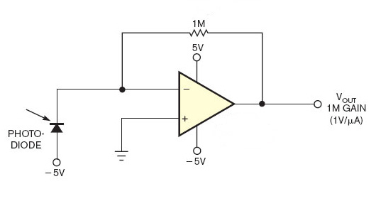
You can convert the photodiode's current to a voltage with a series resistor, or with an opamp transimpedance amplifier:

enter image description here

Note that the diode's anode has to be tied to a voltage more negative than the non-inverting input. I find a surprising number of circuits on the 'Net where the anode is connected to ground. But then, because the diode creates a voltage drop, the opamp can't regulate the output so that the inputs become equal and the output will saturate.

\$\endgroup\$
2
  • \$\begingroup\$ Thanks @stevenvh. This is closest to what I was thinking of, at a very abstract level though. Two further questions: [Q1] Can the photographer's filter + photo-diode, be replaced easily, with single (or array-of) photo-diode(s), with in-built filter, as suggested by Russell in his answer ? [Q2] On a battery (12V) powered circuit, I believe I could tie the -5V to battery's -ve terminal, GND for op-amp with 6V (voltage divider) and +5V of op-amp to say +ve terminal of battery. Right ? \$\endgroup\$
    – bdutta74
    Commented Jul 19, 2012 at 9:57
  • \$\begingroup\$ @icarus74 - the photodiode + filter is like Russell's TCS3210, but then only with the blue and clear channel. In the TCS3210's datasheet you'll see that blue also detects infrared, you'll have to do some processing on all four channels to get actual blue data. The photographic filter may be more restricted to the wavelengths of interest. [Q2]: Yes. \$\endgroup\$
    – stevenvh
    Commented Jul 19, 2012 at 10:05
4
\$\begingroup\$

A very simple approach to determining the color of a surface is to use one photodiode or photoresitor and a number (3, for example, like in RGB) of LEDs of different colors to light the surface.

Then, in a time-multiplexing fashion, each of the LEDs is turned on by itself in sequence to light the surface, and the intensity of the reflected light is measured for each of them.

Example: If using three LEDs, one red, one green, and one blue, this will yield three reflection intensity values, one for each color component, which together, after possible normalization, will give a numerical approximation of the surface's color in some kind of RGB space (which depends on the specific wavelength distributions of the LEDs, of course).

(I will use the RGB-three-color example setup in the following for simplicity, but any number from 1 to n of differently colored lightsources can be used; the more different colors are used the more exact the surface's color may be determined.)

The principle is the same as in a camera's chip: The intensities of the red, blue, and green components of the incoming light are measured independently and the combination of the three intensities determines the color. In the camera, there is one photodetector for each of those three basic colors so that all three intensities can be measured at the same time. What makes this complicated is that three different sensors or three different filters are needed.

The proposal therefore works the other way around: Instead of filtering the light after it is reflected from the surface one can also 'filter' the light before it hits the surface; basically, for your perception it doesn't matter if you put on your blue-tinted sunglasses or if you use a blue light source and no sunglasses instead.

The intensitiy of reflected light measured for each color component (or LED) will yield a (normalized) value in the range of [0.0, ..., 1.0], where 0.0 means that no light is reflected and 1.0 means that a maximum amount of light is reflected. Depending on the color of the surface the intensities will be different for the different light colors (wavelengths).

In every case, you will receive three intensity values, each of which determines the intensity of a certain part of the color spectrum. Each complete measurement thus yields a triplet (r,g,b) which determines the color measured. As in computer graphics, the triplet (0,0,0) represents complete darkness, black; (1,1,1) is brightest white, and any combination (r,g,b) where r == g == b represents some shade of grey. All other possible combinations identify a distinctive point in the RGB-space, defining the color measured. (0.5,0,0) is some medium red, for example, and (0.9,0.9,0) is some relatively bright yellow, etc..

Note:

  1. The photodetector must, of course, be sensitive to all of the (3) used light colors.
  2. The photodetector may need some time to stabilize after switching LEDs before accurate readings can be obtained; photoresistors, for instance, are usually relatively slow. Tens to hundreds of milliseconds may be needed for acceptable precision, minutes for the most exact values.
  3. Once the hardware is set up, it can be easily calibrated to the surface colors of interest by simply measuring a sample of each. This way, no effort needs to be made in trying to determine exact wavelength distributions or relative brightness of the LEDs, or the relative sensitivity of the sensor for those wavelengths.
  4. Normalization of the measured values may be needed before actual use. For example, to compensate for stray light from outside, one more measurement may be taken with all LEDs off and the result will then be subtracted from the values measured when LED lit. Generally, the absolute value measured for each color component is of less significance than the relative difference between them.

Some random pages with 'hands on' on the topic:

http://www.societyofrobots.com/sensors_color.shtml

http://www.instructables.com/id/Color-Detection-Using-RGB-LED/#step1

http://letsmakerobots.com/node/23768

\$\endgroup\$
2
  • \$\begingroup\$ Thanks. Definitely worth a try, and especially so when I aim for detection of a slightly wider set of colours. However, I am not sure I understand the physics behind this principle. A simple photodiode/photoresistor would only detect the intensity, and I think that one can have the same intensity reported for each of R,B,G. So I wonder how this will work. \$\endgroup\$
    – bdutta74
    Commented Jul 19, 2012 at 17:23
  • \$\begingroup\$ Please see my edit and let us know if something still is not clear. \$\endgroup\$
    – JimmyB
    Commented Jul 20, 2012 at 17:45
3
\$\begingroup\$

There are a substantial number of ICs that will do this job with various degrees of capability. I'll break the range into 3 parts, but there are absolute hard and fast boundaries.

(1) At the bottom end are ICs with effectively a single diode sensor per colour, RGB filters and 3 channel output.
An example (not in stock at Digikey) is the Avago ADJD-S311-CR999

(2) Above that are small arrays of photodiodes with RGB filters and maybe also unfiltered cells. Example below.

(3) At the top end are full colour camera ICs at quite reasonable prices. Example below.

Simple and cheap - analog square wave output on R G B luminance channels.
For about $3.50 in stock in 1/s at Digikey - 24 or 64 photodiodes arranged into 4 interleaved groups - 25% each of R, G, B & Clear filters.
Pricing is for the larger IC. Datasheet here

  • The TCS3200 and TCS3210 programmable color light-to-frequency converters that combine configurable silicon photodiodes and a current-to-frequency converter on a single monolithic CMOS integrated circuit.
    The output is a square wave (50% duty cycle) with frequency directly proportional to light intensity (irradiance).
    The full-scale output frequency can be scaled by one of three preset values via two control input pins. Digital inputs and digital output allow direct interface to a microcontroller or other logic circuitry. Output enable (OE) places the output in the high-impedance state for multiple-unit sharing of a microcontroller input line.
    In the TCS3200, the light-to-frequency converter reads an 8 × 8 array of photodiodes. Sixteen photodiodes have blue filters, 16 photodiodes have green filters, 16 photodiodes have red filters, and 16 photodiodes are clear with no filters.
    In the TCS3210, the light-to-frequency converter reads a 4 × 6 array of photodiodes. Six photodiodes have blue filters, 6 photodiodes have green filters, 6 photodiodes have red filters, and 6 photodiodes are clear with no filters.
    The four types (colors) of photodiodes are interdigitated to minimize the effect of non-uniformity of incident irradiance. All photodiodes of the same color are connected in parallel. Pins S2 and S3 are used to select which group of photodiodes (red, green, blue, clear) are active. Photodiodes are 110 μm × 110 μm in size and are on 134-μm centers.

Somewhat dearer. More complex. Far more capable.
For $18 in stock at Digikey you can get a full 5 Mp RGB "color camera" sensor - 2592 x 1944 x 14 fps or VGA at 53 fps. This should meet your need [tm].
Datasheet here

  • The Aptina® MT9P031 is a 1/2.5-inch CMOS activepixel digital image sensor with an active imaging pixel array of 2592H x 1944V. It incorporates sophisticated camera functions on-chip such as windowing, column and row skip mode, and snapshot mode. It is programmable through a simple two-wire serial interface.
\$\endgroup\$
2
  • \$\begingroup\$ Thanks Russell. Not sure if it is the formatting but I cannot clearly make out, if you are talking of 3 options, with 3 set of details, or just 2 options. From cost-bracket perspective, I can afford the photodiode-array approach. Wondering though, if having a single photodiode, versus an array of 4x6, versus a 8x8 one I would really gain much accuracy, in determining the object colour ? I think so, but would like to hear from others. \$\endgroup\$
    – bdutta74
    Commented Jul 19, 2012 at 9:39
  • \$\begingroup\$ @icarus74 - Answer updated. \$\endgroup\$
    – Russell McMahon
    Commented Jul 19, 2012 at 11:14

Your Answer

By clicking “Post Your Answer”, you agree to our terms of service and acknowledge you have read our privacy policy.

Not the answer you're looking for? Browse other questions tagged or ask your own question.