46
\$\begingroup\$

I'll be using a microcontroller to create a PWM signal for motor control. I understand how PWM and duty cycle works, however I am unsure about an ideal frequency. I do not have my motor in yet, so I can't just test it and find out.

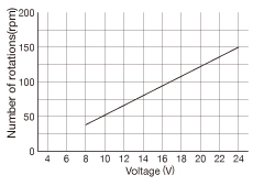
This is the specific performance graph.

The picture depicts a graph of RPM vs Voltage. It's linear from 50 RPM @ 8 V to 150 RPM @ 24 V.

I will not be varying voltage, just the time it receives a given voltage. So can I assume a linear response? At a 10% duty and 24 V supply it would run at a speed of 15 RPM?

If it makes a difference, I'll include the setup. I am running 24 V directly to an H-bridge that controls the motor. Obviously I have two PWM pins going from the MCU to the gates of the two enable MOSFETS.

\$\endgroup\$

5 Answers 5

58
\$\begingroup\$

In short:

You have linear control of the 'speed' by applying a PWM signal, now the frequency of that signal has to be high enough so that your DC Motor only passes the DC component of the PWM signal, which is just the average. Think of the motor as a low pass filter. If you look the transfer function or relationship angular speed to voltage, this is what you have:

$$\frac{\omega(s)}{V(s)}=\frac{K}{\tau s+1} $$ This is the first order model of a DC motor or simply a low pass filter with cutoff frequency $$f_c=\frac{1}{2\pi\tau}$$

Where \$\tau\$ is the motor's time constant. So as long as your frequency is beyond the cutoff, your motor will only see the DC part or the average of the PWM signal and you will have a speed in concordance with the PWM duty cycle. Of course, there are some tradeoffs you should consider if you go with a high frequency.

Long story:

Theoretically, you would need to know the motor's time constant in order to choose the 'right' PWM frequency. As you probably know, the time it takes the motor to reach almost 100 % its final value is $$ t_{\text{final}}\approx 5\tau$$

Your PWM frequency has to be high enough so that the motor (essentially a low pass filter) averages out your input voltage, which is a square wave. Example, let's say you have a motor with a time constant \$\tau=10\text{ ms}\$. I am going to use a first order model to simulate its response to several PWM periods. This is the DC motor model: $$\frac{\omega(s)}{V(s)}=\frac{K}{10^{-3} s+1} $$

Let's let \$k=1\$ for simplicity.
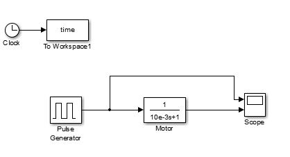
enter image description here

But more importantly here are the responses we're looking at. For this first example, PWM period is \$ 3\tau\$ and the duty cycle is 50 %. Here is the response from the motor:
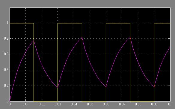
enter image description here

The yellow graph is the PWM signal (50 % duty cycle and period \$ 3\tau=30 ms\$) and the purple one is the speed of the motor. As you can see, the speed of the motor swings widely because the frequency of the PWM is not high enough.

Now let's increase the PWM frequency. The PWM period is now \$ 0.1\tau=1\text{ ms}\$ and duty cycle is still 50 %.
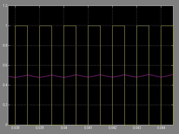
enter image description here

As you can see, now the speed is pretty much constant because the high frequencies components of the PWM signal are being filtered out. In conclusion, I would pick a frequency that is at least $$f_s\geq \frac{5}{2\pi\tau}$$

This is just a very theoretical explanation on how to choose the PWM frequency. Hope it helps!

\$\endgroup\$
13
  • 4
    \$\begingroup\$ Good answer. You might clarify that in saying "the time it takes the motor to reach almost 100% its final value" that you mean final or full current value. Readers may confuse it with 100% speed or who-knows-what? \$\endgroup\$
    – Transistor
    Commented Jun 22, 2016 at 17:27
  • \$\begingroup\$ This was very informative! I am not an EE, so I'm not extremely educated in this. I will likely just try different frequencies until I get a response that I like across the spectrum I need to operate in. However, I will keep this in mind when doing that setup! . I do have one question though. You said these numbers were all very theoretical, but could you give a ball park of the expected time constant? It's a 24 V dc motor that draws at most 300 mA. \$\endgroup\$
    – Nate San
    Commented Jun 22, 2016 at 17:43
  • 1
    \$\begingroup\$ @NateSan Thanks! As one of the answers, which are really good, the best you could do is start with frequencies in the KHz range, like 2KHz for example. There is no way to estimate the time constant based on the given information or at least I don't know. You can find it experimentally, but you're better off just trying different frequencies until you get close to what you want. \$\endgroup\$
    – Big6
    Commented Jun 22, 2016 at 17:56
  • 1
    \$\begingroup\$ The facts presented do not support the conclusion: Both graphs have an average of 0.5. I think this reflects reality, the linearity does not depend on the PWM frequency. The only compromise to be made is current/torque ripple and noise on the lower side, and eddy current and switching losses on the higher side. \$\endgroup\$
    – alain
    Commented Jun 23, 2016 at 13:31
  • 1
    \$\begingroup\$ @PageDavid It's been a moment since I did this, but you can measure this experimentally by applying an input voltage to the motor and see how long it takes for the angular speed to reach 63.2% of it final value. You may have to iterate this a couple of times and find the avg (though it should be fairly close from measurement to measurement). For this you'd need the right equipment, like tachometers/other tools. Maybe this link will help: mech.utah.edu/~me3200/labs/motors.pdf or google "find dc motor time constant"—this is one of the most common experiments in intro controls course. \$\endgroup\$
    – Big6
    Commented May 27, 2019 at 23:22
13
\$\begingroup\$

Your motor is likely geared down, because 150 rpm is only 2.5 revolutions per second. At 50 rpm, your motor will require more than a second to perform one revolution.

That having been said, the switches in your h-bridge don't dissipate much power when they are on (essentially zero volts) or when they are off (zero current). They only have both voltage and current present when they switch, so higher switching frequency means more heat in your FETs.

Stay in the 5-20 kHz range and you probably will be safe. If you go too much lower, the motor current ripple (and torque ripple) may be noticeable, but you can experiment with this. Too much higher and you will be heating up your switches. You may also want to go towards the higher end to get out of the audible range.

\$\endgroup\$
2
  • \$\begingroup\$ It's a motor for a peristaltic pump, I'm not sure about the gearing. So you're saying that if I ran the PWM at 20KHz I could vary the duty cycle between 0 and 100 to get a near linear change in RPM(which translates to pump flow rate for me). \$\endgroup\$
    – Nate San
    Commented Jun 22, 2016 at 15:40
  • 3
    \$\begingroup\$ If the switches heat up it's not because of the operating frequency (not below 1MHz anyway). As you stated, most of the switching losses occur when the FET is neither fully ON or OFF. The trick to keeping them cool is to drive their gate hard enough to minimize Ton and Toff. Choose FETs with low gate charge and low Ton Toff, and low RDSon. \$\endgroup\$ Commented Jun 23, 2016 at 5:46
12
\$\begingroup\$

A practical motor behaves roughly like a resistor and inductor in series with a real motor. For efficient operation you need should switch between connecting the motor to the supply and shorting it out. While the motor is connected to the supply, the current will become more positive. When shorted, it will become more negative. Efficiency will go downhill markedly if the current switches polarity, because the motor will spend part of each cycle trying to mechanically fight what it's doing in other parts.

From the standpoint of the motor itself, efficiency will be at its best when the PWM rate is as high as possible. Two factors limit the optimum PWM rate, however:

  1. Many motors have a capacitor in parallel with them in an effort to minimize electromagnetic interference. Every PWM cycle will need to charge and discharge that cap, wasting a full load of energy. Losses here will be proportional to frequency.

  2. Many H-bridge switches take a certain amount of time to switch; while they are switching, much of the power going into them will be wasted. As the PWM on and off durations shrink toward the point where the bridge is spending most of its active or inactive time switching, switching losses will increase.

What's most critical is that the PWM rate be fast enough that the motor doesn't fight itself. Going faster beyond that will improve motor efficiency somewhat, but at the expense of increase the other aforementioned losses. Provided there isn't too much parallel capacitance, there will generally be a fairly big range of frequencies were PWM losses are minimal and motor current polarity remains forward; a frequency somewhere near the middle of that range will probably be best, but anything within that range should be adequate.

\$\endgroup\$
6
  • \$\begingroup\$ I actually wont be grounding it during the off period, friction will stop the motor very quickly. So I didn't see a reason not to leave it floating between duty periods. \$\endgroup\$
    – Nate San
    Commented Jun 22, 2016 at 17:45
  • 2
    \$\begingroup\$ @NateSan: Because the motor has inductance, current will continue to flow even when you try to switch it off. Shorting the motor will allow the energy to continue doing useful work during the off period, and will reduce the amount of energy you need to dissipate outside the motor \$\endgroup\$
    – supercat
    Commented Jun 22, 2016 at 19:44
  • 2
    \$\begingroup\$ Alternatively, use a flyback diode. For an inductive load (e.g. motor) it's important to have a path for the current when the supply is switched off, to avoid a voltage spike which could kill your switching transistor. \$\endgroup\$ Commented Jun 23, 2016 at 4:52
  • 3
    \$\begingroup\$ @CraigMcQueen: A flyback diode will effectively short out the motor while forward current is continuing, less a 0.7-volt drop. At 24VDC the 0.7V drop may not be a problem, but performance would be better without it. \$\endgroup\$
    – supercat
    Commented Jun 23, 2016 at 13:47
  • 1
    \$\begingroup\$ @supercat: What is your recommended alternative to short the motor when in the "off" state? A second FET? Could you show or refer to an example circuit diagram? \$\endgroup\$ Commented Jun 23, 2016 at 23:10
8
\$\begingroup\$

I designed and worked on a PWM speed/positional control system that drove 16 brushed DC motors some years back. We were buying from Mabuchi, who sold 350M motors a year at the time. They recommended 2 kHz PWM frequency which tallied with recommendations from other sources, including R/C aeroplanes of the time. We had good results and I've used it since.

There's a theory that a frequency above 20 kHz means no whistling/noise but we found that not to be true. I don't know the true physics of it but there is a mechanical movement that you can hear. I, rightly or wrongly, took it to be the sub-harmonics (right phrase?) of the frequency as coils or components try to move ever so slightly at the high frequency but can't keep up.

We found the same when trying out a solenoid driver using PWM. A scope across the solenoid showed the correct test frequencies, first 25 kHz then higher and higher. The whistling noise from the solenoid was clear and unpleasant. We abandoned the PWM approach after a fair amount of testing and experimenting.

I have mobile phone chargers at home that I can clearly hear whistling and I know that their PWM oscillators are running well upwards of 100 kHz. (In fact, I often turn off the one in the kitchen when walking past it because I hear the higher-pitched 'no load' whistle when no phone's connected. I also hear the tone drop to quiter and lower when a phone's first plugged in.)

\$\endgroup\$
2
  • 4
    \$\begingroup\$ With the phone charger, it's not the main switching frequency you hear, it's the low-load pulse-skipping, burst mode or other energy-saving scheme that either decreases the frequency, or makes the switcher wake up and do a burst at intervals that correspond to audible frequency. It's extremely annoying. If the accursed thing has a blinking LED, it will also beep-beep-beep along with the led. \$\endgroup\$
    – bobflux
    Commented Mar 20, 2021 at 17:42
  • 1
    \$\begingroup\$ @bobflux, as said, the charge whistling can be heard changing across all loads whereas SMPS pulse skipping is only at low/off load. The motor and solenoid designs were pure PWM and examined on 'scopes, prototypes for mass production so much time and effort spent to try to resolve it. It'd be nice to say it wasn't like that...but it was like that. \$\endgroup\$
    – TonyM
    Commented Mar 20, 2021 at 18:52
4
\$\begingroup\$

Sometimes its desirable to stay above the audible frequency (20 kHz) if the motor and driver supports it. If its were a person can hear it, a constant high pitched frequency can be annoying. Younger people can hear it, after age 40, it tapers off.

\$\endgroup\$

Your Answer

By clicking “Post Your Answer”, you agree to our terms of service and acknowledge you have read our privacy policy.

Not the answer you're looking for? Browse other questions tagged or ask your own question.