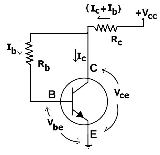
In BJT biasing the voltages Vbe and Vce are always present in calculations.
Is the voltage Vbc absent from any equation because one of the collector, base and emitter is grounded or any other reason concerning the theory of semiconductors?

-
\$\begingroup\$ By definition Vbc = Vce - Vbe, but why would that matter? Even if none of the BJT terminals were grounded, the relationship between Vbe and Ib and the relationship between Ib and Ic is most relevant to biasing the transistor. In common-emitter configuration (emitter is signal ground for both input and output), the input is either Ib or Vbe, and the output is either Ic or Vce. The voltage difference Vbc can be calculated, but isn't very interesting because it's neither an input nor an output, just an irrelevant voltage difference. \$\endgroup\$– MarkUCommented Aug 13, 2016 at 23:12
-
2\$\begingroup\$ Because Vbc isn't (usually) very interesting. (Except when it goes negative, or when you are worried about Miller capacitance in high frequency applications) \$\endgroup\$– user16324Commented Aug 13, 2016 at 23:46
-
1\$\begingroup\$ IMHO due to prevalence of the common-emitter circuit. \$\endgroup\$– Incnis MrsiCommented Aug 27, 2016 at 20:04
1 Answer
You are incorrect in your titled assertion. But I can guess where it comes from.
Most people use the simplest concepts they need to get the job done. They are concerned about the forward voltage, \$V_{BE}\$, which is somewhat impacted by the collector current and very much impacted by temperature... so that's important... and \$V_{CE}\$ is immediately related to whether or not the BJT is saturated or not and this impacts very basic questions about available \$\beta\$, likely dissipation and temperature of operation, which are also pretty important. Besides, if you know \$V_{BE}\$ and \$V_{CE}\$ then you know \$V_{BC}\$. You might care about that, too. For example, the Early effect... But it's of secondary importance.
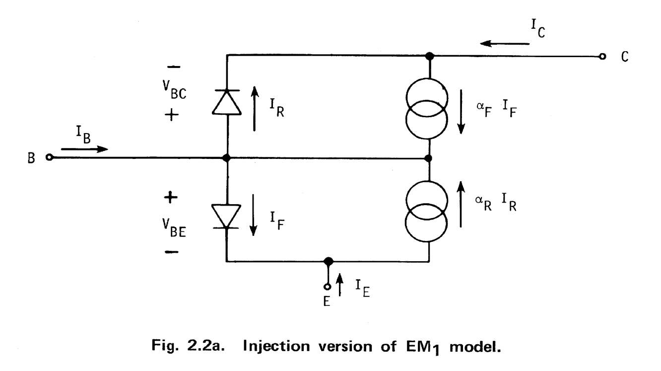
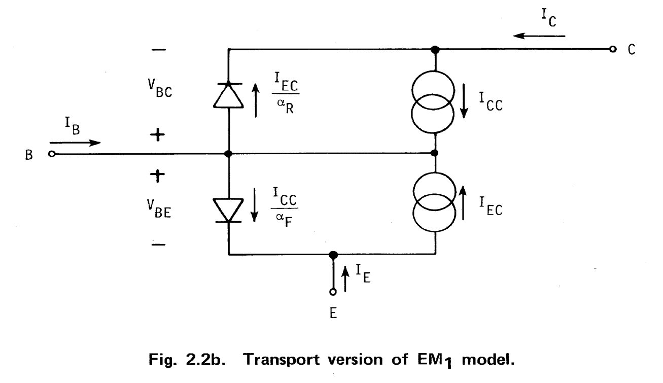
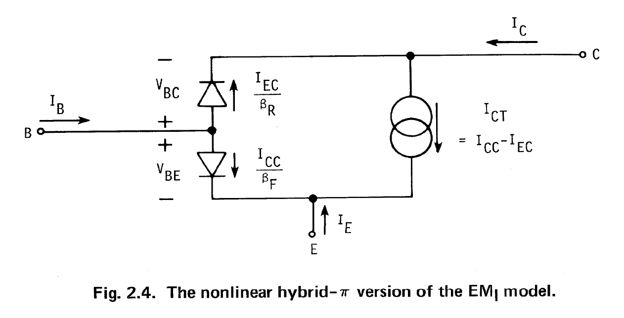
But you are wrong, anyway. The first model of the transistor to learn about is the Ebers-Moll model. It's level 1 model includes three distinct ways of looking at the BJT: transport, injection, and hybrid-pi. They are equivalent views, but they have different areas where they are easier to apply.
Let's look at the injection model first (addressing itself to diode currents):

- \$I_F = I_{ES} \cdot \left[ e^{\frac{q\cdot V_{BE}}{k\cdot T}} - 1 \right] \$
- \$I_R = I_{CS} \cdot \left[ e^{\frac{q\cdot V_{BC}}{k\cdot T}} - 1 \right] \$
- \$ I_C = \alpha_F \cdot I_F - I_R \$
- \$ I_B = \left( 1 - \alpha_F \right) \cdot I_F + \left( 1 - \alpha_R \right) \cdot I_R \$
- \$ I_E = -I_F + \alpha_R \cdot I_R \$
Now, the transport version (addressing itself to collected currents):

- \$I_{CC} = I_S \cdot \left[ e^{\frac{q\cdot V_{BE}}{k\cdot T}} - 1 \right] \$
- \$I_{EC} = I_S \cdot \left[ e^{\frac{q\cdot V_{BC}}{k\cdot T}} - 1 \right] \$
- \$ I_C = I_{CC} + \left[ -\frac{1}{\alpha_R} \right] \cdot I_{EC} \$
- \$ I_B = \left[ \frac{1}{\alpha_F} - 1 \right] \cdot I_{CC} + \left[ \frac{1}{\alpha_R} - 1 \right] \cdot I_{EC} \$
- \$ I_E = \left[ -\frac{1}{\alpha_F} \right] \cdot I_{CC} + I_{EC} \$
Finally, the non-linear hybrid-\$\pi\$ (nice, because linearizing it in the small-signal case leads directly to the well-known linear small-signal hybrid-\$\pi\$ model):

- \$\frac{I_{CC}}{\beta_F} = \frac{I_S}{\beta_F} \cdot \left[ e^{\frac{q\cdot V_{BE}}{k\cdot T}} - 1 \right] \$
- \$\frac{I_{EC}}{\beta_R} = \frac{I_S}{\beta_R} \cdot \left[ e^{\frac{q\cdot V_{BC}}{k\cdot T}} - 1 \right] \$
- \$I_{CT} = I_{CC} - I_{EC}, \rm{(generator \,\, current)}\$
- \$ I_C = \left( I_{CC} - I_{EC} \right) - \frac{I_{EC}}{\beta_R} \$
- \$ I_B = \frac{I_{CC}}{\beta_F} + \frac{I_{EC}}{\beta_R} \$
- \$ I_E = -\frac{I_{CC}}{\beta_F} - \left( I_{CC} - I_{EC} \right) \$
As you can easily see now, \$V_{BC}\$ figures quite prominently in the most basic and first level BJT modeling. And it doesn't stop there. It's present in EM1 (DC perspective), EM2 (more accurate DC with 3 new constant valued resistors in each lead, 1st order modeling of charge storage for freq. and time), EM3 (basewidth modulation - Early effect, variation of forward current gain with collector current, other DC and AC improvements, etc), Gummel-Poon (basewidth mod and \$\beta\$ vs I, AC and variations with ambient temps, etc), modified versions of those, and even into the latest models. You just haven't been exposed to even the first level of BJT modeling, yet. That's all. That's because for many (if not most) needs, you can simplify the basic BJT EM1 model still further and ignore quite a bit and still get by, okay.
Full disclosure: The three images shown above were taken directly from Ian Getreau's "Modeling The Bipolar Transistor," which was originally written circa 1974 by Ian, then an employee at Tektronix (which at the time had an "STS" [semiconductor test systems] division.) I received my first copy of the book in 1979, when I started as an employee at Tektronix. Ian has since secured the rights from Tektronix (in 2009) and has republished it through Lulu. So it's still available today. [I have never met Ian nor do I receive anything from him for sales of the book or for any other reason. But I did help him get it republished because the book is unique and needed to become available, again.] Half of his book is dedicated to various techniques one can use to extract, through experiment, various BJT parameter values for the models he documents (which include up through Gummel-Poon.) It holds a unique and special place in the literature.
-
2\$\begingroup\$ Excellent answer. There sure is a lot going on behind the scenes in just about everything beyond the simplest, easily-hand-calculated models. \$\endgroup\$ Commented Aug 14, 2016 at 1:12
-
1\$\begingroup\$ I actually worked with Ian Getreu (he's local to me) to get his book on the BJT republished. It's unique -- nothing else since can replace having a copy of it. It was originally published (and given out free) by Tektronix, back in 1976 when Tek had its STS (semiconductor test systems) division. The title is "Modeling The Bipolar Transistor." Personally, I think it is a must have and must study book. It really helps you understand things. After theory and practical details, the 2nd half covers many, many ways to set up and extract parameter details from a BJT, too. Nothing like it. \$\endgroup\$– jonkCommented Aug 14, 2016 at 1:22
-
\$\begingroup\$ Fancy. If I did much more analog stuff, I'd definitely want a copy. Particularly if I worked in the part of the test and measurement company that builds STS systems. However, I'm (happily) on the digital side of development that's in a rather different application area. \$\endgroup\$ Commented Aug 14, 2016 at 1:54
-
\$\begingroup\$ It's not a popular book! ;) And I don't think most people really need to know that much about a BJT in order to get by in life. But at least lulu has it available, now. (I have no financial interest in the book -- Ian gets everything.) It was unobtainium for a few decades before. Thanks for the kind comment, too. \$\endgroup\$– jonkCommented Aug 14, 2016 at 2:02
-
1\$\begingroup\$ @TonyStewartEE75 It's the only answer here that provides all three original level 1 equivalent Ebers-Moll models. I reference this, frequently, now. I will not remove it for love or money. \$\endgroup\$– jonkCommented Aug 11, 2021 at 8:42
