2
\$\begingroup\$

schematic

simulate this circuit – Schematic created using CircuitLab

Description:

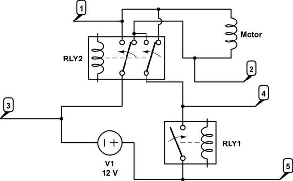
RLY1 relay switches 12v on or off. RLY2 changes direction of current flow to the motor. I have flyback diodes on RLY1 & RLY2 coils. The relays are switched by an Arudino through a transistor switch. The relays are 12v, as is the motor. The motor draws about 1.5A in normal use.

The code ensures that RLY1 always turns off before RLY2 changes direction. Furthermore there is a 1 second pause between any RLY1 and RLY2 action.

Questions:

  1. Where should the snubber diode go to protect RL1? (Between 5 & 4 would flow current back into +12v which seems like a bad idea. Between 1 and 2 wouldn't work because when the motor is running in one of the two directions the diode would short. I have reviewed lots of diagrams and descriptions but can't get my head around the correct location. )

  2. Am I correct that the objective is to use the diode voltage drop (.6v) to consume the inductive kickback as current cycles through a circuit containing the diode.

  3. Is inductive kickback a risk to RLY2? I know it is to RLY1.

\$\endgroup\$
1
  • \$\begingroup\$ Welcome to EE.SE. Your schematic is difficult to read - particularly the RL2 contacts. There is a schematic tool on the editor toolbar. It's very easy to use and has relay symbols built in. Update your question and you will get answers.. \$\endgroup\$
    – Transistor
    Commented Jul 18, 2017 at 12:59

3 Answers 3

3
\$\begingroup\$

schematic

simulate this circuit – Schematic created using CircuitLab

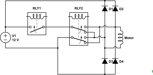
Figure 1. OP's circuit redraw with positive voltages on top and negative on bottom.

schematic

simulate this circuit

Figure 2. Using snubber diodes. In this configuration the maximum voltage that can appear across the contacts is 12 V + 2 x 0.7 V = 13.4 V.

schematic

simulate this circuit

Figure 3. Back to back Zener diodes. Zener diode voltage should be a few volts above supply voltage to prevent turn on or high leakage around the knee voltage.

The solution of Figure 3 is probably the most elegant as it uses only two components which can be placed at the motor and requires no additional wiring.

Where should the snubber diode go to protect RL1? (Between 5 & 4 would flow current back into +12v which seems like a bad idea. Between 1 and 2 wouldn't work because when the motor is running in one of the two directions the diode would short. I have reviewed lots of diagrams and descriptions but can't get my head around the correct location. )

You are correct that there can be a problem. Since you are trying to protect the contacts the best place to do the protection is at the motor (but see Figure 4, etc.).

Am I correct that the objective is to use the diode voltage drop (.6v) to consume the inductive kickback as current cycles through a circuit containing the diode.

Yes, but 0.6 V isn't a magic number. You just need to keep it low enough to prevent arcing. Figure 3 shows a possible solution. In either case one Zener diode is forward biased (0.7 V drop) and the other is reverse biased. The reverse biased one will limit maximum voltage to the sum of the 0.7 V + \$ V_{Zener} \$. This will work in either polarity or if RLY2 is switched while live.

Is inductive kickback a risk to RLY2? I know it is to RLY1.

Not if it doesn't switch the live load.

schematic

simulate this circuit

Figure 4. If RLY1 does all the load switching and RLY2 only switches when power is off then a diode placed as shown will suffice.

As @user28910 points out, Figure 4 will suffice if sequencing can be guaranteed.

\$\endgroup\$
2
  • \$\begingroup\$ I understand that the inductive kickback is high voltage but very low current, is that correct? Therefore, are there wattage considerations for the Zeners in figure 3 or the single diode in figure 4? I've measured the motor and it draws around 1.5A throughout my use case. It's stall rating is 10Amps but my use case won't stall it. \$\endgroup\$
    – Squats
    Commented Jul 19, 2017 at 1:48
  • \$\begingroup\$ The easy way to think of this is that capacitors try to keep the voltage across them constant; inductors try to keep the current through them constant. If the motor is drawing 1.5 A when the relay contact opens it tries to continue drawing 1.5 A the instant afterwards. This causes the voltage to rise high enough to cause the air to conduct so that the 1.5 A continues to flow but the effort causes it to quickly drop to zero. Therefore the snubber needs to be able to handle the peak (surge) current but their average current rating can be quite low. @Tony addresses this better than my answer. \$\endgroup\$
    – Transistor
    Commented Jul 19, 2017 at 6:10
2
\$\begingroup\$

"Normal Motor current" has no meaning, unless the Rated current and Start currents are both given. I would expect more than "No Load " current but how much load is irrelevant when direction reverse relay is activated, while running at full speed.

This is because the Motor acts as a generator of Back EMF to reduce the no load current to just losses at some RPM speed. ( friction, Eddy current, minimal conduction losses from excitation reactance + commutation losses).

Thus the relay contact protect is not simply to absorb the current from Close to open circuit but also from intermediate open to close alternate voltage circuit where the Surge current will now be 200%*Istart compared to start surge current and not just for the L/R time constant but now for the duration of power applied and change in Kinetic Energy from moving mass. E=½mv²

Relay Contact current ratings for DC are normally derated 50 to 75% due to the sustained arc when open and thermal energy can be greater due to the lack of zero crossing current in AC which can extinguish an arc.

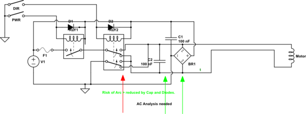
Thus snubbers With a clamping voltage contact-open interval but not in the polarity reversal conduction interval while the motor draws 2x the I_start or \$I_{surge}\$ completion of the voltage reversal. Pd dissipation in the snubbers must consider the coil energy and back EMF duration for slowing down.

The most efficient Snubber clamps would be a full wave bridge with the DC source to +/- and AC inputs to Motor rated for starting Energy of motor or using watt-second curves for the Diode Bridge and thermal resistance..
schematic

simulate this circuit – Schematic created using CircuitLab

Normally small DC motors are rated at 8x to 10x Rated load full speed current. THis means Voltage reversal at full speed is 16 to 20x full rated current.

Some method to limit surge current must be considered to extend the reduced life expectancy from doing this. e.g. PWM, V/F control, NTC surge limiter for each polarity.

Snubber part may consider using bipolar Zeners, TVS or MOV's or choosing RC loads where RC=L/DCR and R=DCR, but requires Joule and thermal calculations to stop the motor from arc voltage that could short out V+ to GND in the relay contacts on either Pole in the DPDT contact arrangement.

Relay current must be SPECIFIED for DC Hp or Idc_surge or derated by at least 50% of max rated current of motor. Imax and relay contacts appropriately selected to handle 2x to 5x rated motor current, Imax. MTBF curves for Relays are avail. from OMRON site due to DC motor surge currents and duty cycle of events. THese events reduce MTBF in a logarithmic scale.

Remember I_start and I_rated are NOT the same and your I_normal , I expect is less than I_rated.

If the DC motors are small enough or contacts rated for Surge current for the duration of time to stop the motor, a configuration could be used at low duty cycle rates to stop the motor quickly by shorting out the windings. Overall motor dissipation increases briefly and must be included with the operating temperatures and rise from these events, but can also be done for most small DC motors.
\$\endgroup\$
1
\$\begingroup\$

(1) The diode would go between 3 and 4, 4 being the cathode. (2) The objective is to provide an alternative path for the motor current, since the motor has inductance which means energy storage. The energy is dissipated in the diode drop as well as the motor winding resistance. (3) Depends. It is only a risk if RLY2 is opened while current is flowing in the motor. In that case the diode won't offer protection.

\$\endgroup\$
3
  • \$\begingroup\$ Adding a diode between 3 and 4 will protect RLY1 contacts but does not protect RLY2 contacts. \$\endgroup\$
    – Transistor
    Commented Jul 18, 2017 at 14:41
  • \$\begingroup\$ @Transistor - Yes, I mentioned that in the last sentence. It's not an issue, unless there is a need to do a reversal so quickly that there is no time to open RLY1 prior to switching RLY2 \$\endgroup\$
    – user28910
    Commented Jul 18, 2017 at 14:55
  • \$\begingroup\$ You are correct. \$\endgroup\$
    – Transistor
    Commented Jul 18, 2017 at 20:27

Your Answer

By clicking “Post Your Answer”, you agree to our terms of service and acknowledge you have read our privacy policy.

Not the answer you're looking for? Browse other questions tagged or ask your own question.