3
\$\begingroup\$

This keeps coming back in every single class, and I still don't have a clear idea of what it is. I keep seeing certain statements in other explanations such as "seen by X", "looking into Y" and so on. However, I don't quite get what that means?

Could you explain to me what they are intuitively, where we place them on the circuit, how we calculate them, and what would be a desired value for them?

\$\endgroup\$
3
  • \$\begingroup\$ To begin with are you clear on what an impedance or resistance is? \$\endgroup\$
    – John D
    Commented Feb 22, 2019 at 19:58
  • \$\begingroup\$ Have you studied Thévenin's theorem? \$\endgroup\$
    – Shamtam
    Commented Feb 22, 2019 at 20:30
  • \$\begingroup\$ I am pretty clear on both impedance/resistance, and Thevenin's Theorem \$\endgroup\$ Commented Feb 24, 2019 at 23:03

3 Answers 3

5
\$\begingroup\$

schematic

simulate this circuit – Schematic created using CircuitLab

Resistance is the load to DC. Impedance is the load to AC.

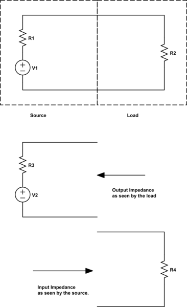
Any circuit will have two parts; the load and the source. The source supplies power to the load. Any circuit can be simplified down to these components. There is no such thing as a perfect source. With a load applied the voltage of that source will droop. In this Thevenin equivalent circuit, there is a resistor in series with an ideal voltage source to simulate the droop. When more current is drawn from the supply the resistor drops more voltage reducing the available voltage to the load. There is also a Norton equivalent with a current source and a resistor in parallel. This resistor R1, in this case, is the output impedance.

The load then has the input impedance. Simply put, it's the impedance of the load. Regardless of how complicated the load is it can always be simplified down to a single resistor.

The importance of input and output impedance is matching them properly. Suppose a signal passes through a filter and then to an ADC of a microcontroller. The filter, in this case, is the source and the ADC is the load. The sampling of the ADC causes a current draw on the line. This can be simulated by a resistor. This resistor is the input impedance of the ADC. Suppose it is 1k ohm. The filter will also simplify down to a voltage source and a resistor. That resistor is the output impedance of the filter. That resistor is important because it forms a voltage divider with the input impedance of the ADC. If the output impedance is 1k ohm then you get a 50% voltage divider. Any signal that comes out of the filter will be reduced by 50%. Often this level of attenuation is not acceptable.

This could be solved by a buffer stage between the filter and the ADC. The buffer has a very high input impedance and a very low output impedance. Suppose 1M ohm and 10 ohm respectively. The input to the buffer then has an attenuation of less than 1% and the input to the ADC also has an attenuation of less than 1%. Combined that is an attenuation of less than 2% and that is usually acceptable.

The calculation of the Thevenin and Norton equivalents is outside of a standard answer and I will leave it up to you to learn them.

\$\endgroup\$
2
  • \$\begingroup\$ I think the comment in your circuit should read "output impedance as seen by the load". \$\endgroup\$
    – TimWescott
    Commented Feb 22, 2019 at 22:38
  • \$\begingroup\$ Is there an elaboration for a situation the load not being connected to the input source? In this case, the output voltage would just be any other Thevenin equivalents the output would encounter, correct? \$\endgroup\$ Commented Dec 14, 2023 at 16:35
1
\$\begingroup\$

For example, take a 9V battery. It does not always have 9V at the terminals, the more current you take out of the battery, the more the voltage will drop from the original 9V. It can be modeled as internal resistance, so this is the output impedance of a battery.

Same can be said about for example analog video or digital audio connections. As these connections use coaxial cables with 75 ohms of characteristic impedance (not DC resistance but the impedance seen by electrical waves), these input connectors are terminated with input impedance of 75 ohms to avoid reflections (think waves in water hitting a wall, they reflect back unless the wall has similar density than water does). For this reason the output connectors also drive the coaxial cable with 75 ohms impedance, so that anything reflecting back to will be dampened as well. So if the signal voltage is 1 Volt into a terminated 75 ohm input, it means the unterminated voltage at output connector would be 2 Volts.

\$\endgroup\$
1
\$\begingroup\$

Mathematically, the output resistance or impedance of a device is the derivative $$r_{out}=\frac{dv_{out}}{di_{out}}$$ where \$i_{out}\$ is considered positive when it flows in to the device (the passive current convention). If we only consider the DC (or quasi-static) behavior, we call this a resistance. If we consider the AC steady-state behavior, we call this an impedance, and we usually change the symbol to \$z_{out}\$.

Similarly, the input resistance or impedance is $$r_{in}=\frac{dv_{in}}{di_{in}}.$$ Again, the current is considered positive when it flows in to the device.

As the other answer has said, when \$r_{out}\$ is positive we get the very usual behavior that when the current out of an amplifier increases (under the passive current convention, we'd say the output current becomes more negative), the output voltage drops, and vice versa. Similarly if \$r_{in}\$ is positive and we increase the input voltage, we will (as we usually expect) drive more current in to the input terminal.

There are some devices with negative port resistance. For example, a buck regulator driving a constant load will need to draw more input current if its input voltage decreases, meaning it has a negative input resistance.

\$\endgroup\$

Your Answer

By clicking “Post Your Answer”, you agree to our terms of service and acknowledge you have read our privacy policy.

Not the answer you're looking for? Browse other questions tagged or ask your own question.