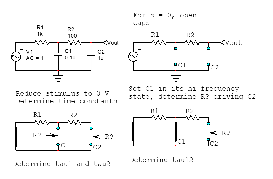
Your circuit shows two cascaded \$RC\$ filters. You can determine the transfer function of this simple circuit using the fast analytical circuits techniques or FACTs. Simply reduce the excitation (the input voltage) to 0 V and "look" through the connecting terminals of a capacitor (which is temporarily disconnected) to determine the resistance \$R\$ you see. That resistance multiplied by the capacitance forms the individual time constant \$\tau\$ you need. The below sketch shows how to do this:

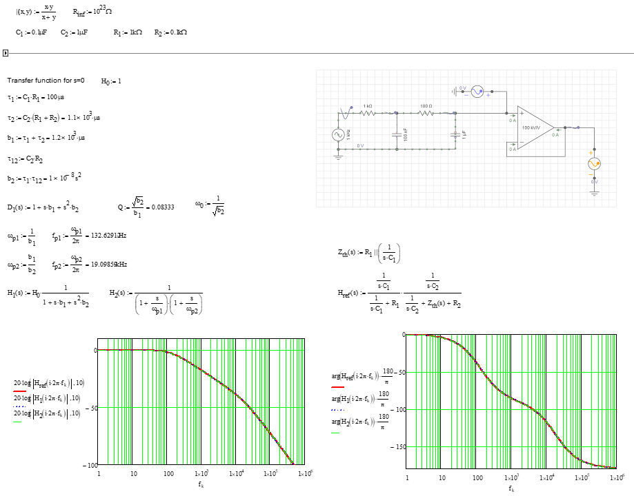
Once you have determined the time constants, you can assemble them in the way I have described in the book I wrote on the subject. The below Mathcad sheet shows the final result:

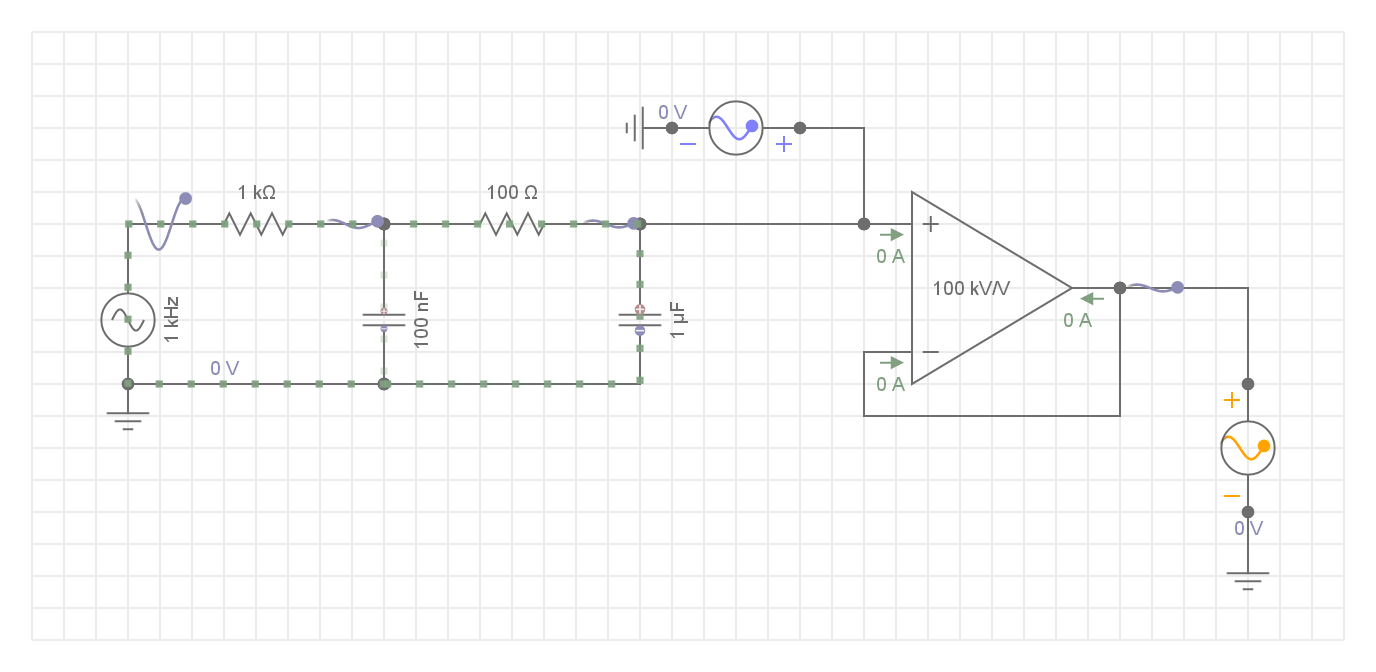
The op-amp is wired as a voltage follower and shields the filter from the load you will connect on the output. Its presence does not affect the transfer function if we consider a perfect element.


