1
\$\begingroup\$

Have I obtained the correct simplified transfer function for this RLC circuit?

I am trying to obtain the transfer function for the following RCL circuit. However, the response of the TF that I obtain doesn't correlate to the response of the circuit itself when I simulate it. Please see below:

enter image description here

Therefore, I have obviously done something wrong. I have spent a good couples of days and plenty of scrap papers trying to see where I have missed something, but I keep on arriving at the same answer.

So, in order to save myself the headache of repeatedly doing the same thing only to obtain the same outcome, I've decided to put my dilemma to the community!

Below is my working out from the mid-way point to the end result and if anyone can spot or point out what I have missed, I would really appreciate it.

So the starting expression is:

$$ I_2(s)((\frac{C_2Ls^3+C_2(R_1+R_2)s+1}{C_2Ls^2+C_2R_1s})(\frac{C_1Ls^2+C_1R_1s+1}{C_1s}))-I_2(s)(Ls+R_1)=E_i(s)\tag{1} $$

$$ I_2(s)((\frac{C_2Ls^3+C_2(R_1+R_2)s+1}{C_2Ls^2+C_2R_1s})(\frac{C_1Ls^2+C_1R_1s+1}{C_1s})-(Ls+R_1))=E_i(s) $$

$$ I_2(s)(\frac{(C_2Ls^2+C_2(R_1+R_2)s+1)({C_1Ls^2+C_1R_1s+1})}{(C_2Ls^2+C_2R_1s)(C_1s)})-(Ls+R_1))=E_i(s) $$

$$ I_2(s)(\frac{(C_2Ls^2+C_2(R_1+R_2)s+1)(C_1Ls^2+C_1R_1s+1)-(C_1C_2Ls^3+C_1C_2R_1s^2)(Ls+R_1)}{(C_1C_2Ls^3+C_1C_2R_1s^2)})\tag{2}$$

Expanding the numerator for the positive term

$$ (C_2Ls^2+C_2(R1+R2)s+1)(C_1Ls^2+C_1R_1s+1)$$

$$ (C_2Ls^2)(C_1Ls^2) + (C_2Ls^2)(C_1R_1s) + (C_2Ls^2)(1) + (C_2(R_1+R_2)s)(C_1Ls^2) + (C_2(R_1+R_2)s)(C_1R_1s)+(C_2(R_1+R_2)s)(1)) + (1)(C_1Ls^2) + (1)(C_1R_1s) + (1)(1) $$

$$ (C_1C_2L^2s^4) + (C_1C_2R_1Ls^3) + (C_2Ls^2) + (C_1C_2L(R_1+R_2)s^3) + (C_1C_2R_1(R_1+R_2)s^2) + C_2(R_1+R_2)s + (C_1Ls^2) + (C_1R_1s) + 1 $$

$$ C_1C_2L^2s^4 + C_1C_2R_1Ls^3 + C_2Ls^2 + C_1C_2L(R_1+R_2)s^3 + C_1C_2R_1(R_1+R_2)s^2 + C_2(R_1+R_2)s + C_1Ls^2 + C_1R_1s + 1 $$

$$ C_1C_2L^2s^4 + C_1C_2R_1Ls^3 + C_2Ls^2 + C_1C_2R_1Ls^3 + C_1C_2R_2Ls^3 + C_1C_2R_1^2s^2 + C_1C_2R_1R_2s^2 + C_2(R_1+R_2)s + C_1Ls^2 + C_1R_1s + 1 $$

$$ C_1C_2L^2s^4 + 2C_1C_2R_1Ls^3 + C_2Ls^2 + C_1C_2R_2Ls^3 + C_1C_2R_1^2s^2 + C_1C_2R_1R_2s^2 + C_2(R_1+R_2)s + C_1Ls^2 + C_1R_1s + 1 \tag{3}$$

Expanding the numerator for the negative term

$$ -(C_1C_2Ls^3+C_1C_2R_1s^2)(Ls+R_1)$$

$$ -((C_1C_2Ls^3)(Ls)+(C_1C_2Ls^3)(R_1)+(C_1C_2R_1s^2)(Ls)+(C_1C_2R_1s^2)(R_1))$$

$$ -(C_1C_2L^2s^4 + C_1C_2R_1Ls^3 + C_1C_2R_1Ls^3 + C_1C_2R_1^2s^2)\tag{4}$$

Subtracting \$(4)\$ from \$(3)\$

$$ C_1C_2L^2s^4 + 2C_1C_2R_1Ls^3 + C_2Ls^2 + C_1C_2R_2Ls^3 + C_1C_2R_1^2s^2 + C_1C_2R_1R_2s^2 + C_2(R_1+R_2)s + C_1Ls^2 + C_1R_1s + 1 -C_1C_2L^2s^4 - C_1C_2R_1Ls^3 - C_1C_2R_1Ls^3 - C_1C_2R_1^2s^2 $$

$$ C_1C_2L^2s^4 + 2C_1C_2R_1Ls^3 + C_2Ls^2 + C_1C_2R_2Ls^3 + C_1C_2R_1^2s^2 + C_1C_2R_1R_2s^2 + C_2(R_1+R_2)s + C_1Ls^2 + C_1R_1s + 1 - C_1C_2L^2s^4 - 2C_1C_2R_1Ls^3 - C_1C_2R_1^2s^2 $$

$$ C_2Ls^2 + C_1C_2R_2Ls^3 + C_1C_2R_1R_2s^2 + C_2(R_1+R_2)s + C_1Ls^2 + C_1R_1s + 1 $$

Combining like terms

$$ C_1C_2R_2Ls^3 + (C_1(C_2R_1R_2 + L)+ C_2L)s^2 + (C_2(R_1+R_2) + C_1R_1)s + 1 $$

Therefore, I get

$$ I_2(s)\frac{C_1C_2R_2Ls^3 + (C_1(C_2R_1R_2 + L)+ C_2L)s^2 + (C_2(R_1+R_2) + C_1R_1)s + 1}{C_1C_2Ls^3+C_1C_2R_1s^2} = E_i(s)$$

And I arrive at this final transfer function each and every time:

$$ \frac{I_2(s)}{E_i(s)}=\frac{C_1C_2Ls^3+C_1C_2R_1s^2}{C_1C_2R_2Ls^3 + (C_1(C_2R_1R_2 + L)+ C_2L)s^2 + (C_2(R_1+R_2) + C_1R_1)s + 1} \tag{5}$$

Therefore, if anyone has noted any step(s) that I might have missed, I would really appreciate it, if you could please point it out :)

\$\endgroup\$
17
  • \$\begingroup\$ Algebra soup, again? Did you first work out the unitless transfer function for Ex/Ei, first? Because you can use the same technique again with that, if you do (as I mentioned before.) Also, did you get sympy, yet? I definitely encourage you to be able to work this with your fingers and some sand. No question. But at some point, it's helpful to get a tool that "just works right" and you can then often use it to show you your own errors. \$\endgroup\$
    – jonk
    Commented Apr 10, 2021 at 3:34
  • \$\begingroup\$ I C a lot of el-seas and would expect the answer to have an equivalent parallel C and or series C result instead of just product terms. Have you tried KVL or Thevenin or other approaches to impedance? Pretend each component is just Z(s) for Z1 to Z5 \$\endgroup\$
    – D.A.S.
    Commented Apr 10, 2021 at 3:34
  • \$\begingroup\$ By the way, I think your bottom formula may be right. \$\endgroup\$
    – jonk
    Commented Apr 10, 2021 at 4:11
  • \$\begingroup\$ @jonk hahaha. Unfortunately :) Tbh, I'm still not too clear on how to obtain $E_o(s)/E_i(s)$ from $I_2(s)/E_i(s)$ and if what I'm getting is actually $I_2(s)/E_i(s)$ or $E_o(s)/E_i(s)$, given as somestimes the TF works without the added impedancce at the output and other times the added impedance gives a different response to what is expected. So, i'm still trying to figure a lot of things out atm :) But, I do need to get onto the sympy thing, if it'll make my life easier! \$\endgroup\$
    – aLoHa
    Commented Apr 10, 2021 at 4:31
  • 1
    \$\begingroup\$ @aLoHa As per the other answers until now, all you have to do is to express \$I_2\$ as a function of the voltage across \$C_2\$: \$I_2=V_2sC_2\$. This means the final expression will be \$\dfrac{V_2sC_2}{E_i}\$, with an extra \$sC_2\$ in the numerator, which makes the whole right hand expression be divided by it, leaving you with the desired transfer function. If you visually compare the two responses then you'll notice that the difference between them is a slope; in this case, the one given by \$sC_2\$. \$\endgroup\$ Commented Apr 10, 2021 at 7:22

2 Answers 2

3
\$\begingroup\$

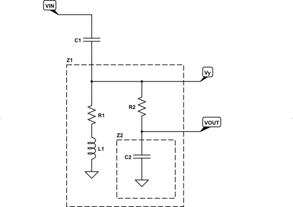
Your schematic is as follows:

schematic

simulate this circuit – Schematic created using CircuitLab

Above, you can see that \$R_2\$ and \$Z_2\$ form a voltage divider that divides \$V_Y\$ into \$V_\text{OUT}\$. It follows that:

$$\begin{align*} \text{Each Stage} &\left\{ \begin{array}{rl} V_\text{OUT} &= V_Y\,\frac{1}{1+\frac{R_2}{Z_2}}&\text{where}&Z_2 &= \left(Z_{C_2}\mid\mid \infty\right)=Z_{C_2}\\\\ V_Y &= V_\text{IN}\,\frac{1}{1+\frac{Z_{C_1}}{Z_1}}&\text{where}&Z_1 &= \left(Z_{L_1}+R_1\right)\mid\mid \left(Z_2 + R_2\right) \end{array} \right.\\\\ &\therefore \frac{V_\text{OUT}}{V_\text{IN}}=\left[\frac{1}{1+\frac{Z_{C_1}}{Z_1}}\right]\cdot\left[\frac{1}{1+\frac{R_2}{Z_2}}\right]\\\\ &\therefore \frac{I_{C_2}}{V_\text{IN}}=\left[\frac{1}{1+\frac{Z_{C_1}}{Z_1}}\right]\cdot\left[\frac{1}{1+\frac{R_2}{Z_2}}\right]\cdot\bigg[C_2\,s\bigg] \end{align*}$$

Let's do this in sympy:

var('l1 c2 r1 r2 c1 vy vout vin')
zc1=1/s/c1                               # C1 impedance
zc2=1/s/c2                               # C2 impedance
zl1=s*l1                                 # L1 impedance
z2=zc2                                   # Z2 is just C2's impedance
z1=(zl1 + r1)*(z2+r2)/(zl1+r1+z2+r2)     # Z1 = parallel combination, as shown
f1=1/(1+zc1/z1)                          # first fraction
f2=1/(1+r2/z2)                           # second fraction
simplify(f1*f2*c2*s)                     # transfer function of I(C2)/V(IN)
    c1*c2*s**2*(l1*s + r1)/(c1*s*(l1*s + r1)*(c2*r2*s + 1) + c2*s*(l1*s + r1 + r2) + 1)
simplify(f1*f2)                          # transfer function of V(x)/V(IN)
    c1*s*(l1*s + r1)/(c1*s*(l1*s + r1)*(c2*r2*s + 1) + c2*s*(l1*s + r1 + r2) + 1)

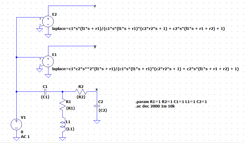
Then I just built this schematic:

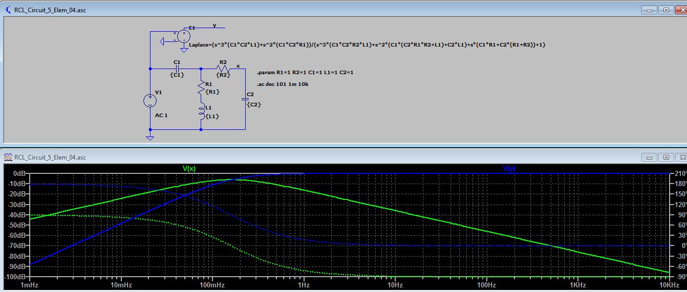
enter image description here

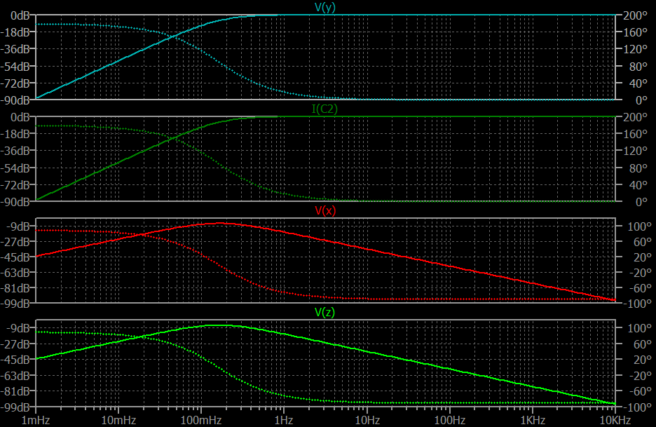
And got this result:

enter image description here

So what's the problem?? I think you need to look more closely either at your algebra process or else for typos in your laplace function. I used a direct "copy/paste" operation directly from sympy to LTspice, to minimize the chances for error.

\$\endgroup\$
5
  • \$\begingroup\$ Thanks for that. Sometimes, it's quite dififcult to see the woods from the trees when you have several papers of algebra littered all of the place :) and I haven't quite yet mastered the syntax for LTspice. \$\endgroup\$
    – aLoHa
    Commented Apr 10, 2021 at 16:45
  • \$\begingroup\$ I believe that I may already have Sympy, as I have Python packages already installed on my PC. So, I'll get back to you via the chatroom on how to go about installing the Sympy package! \$\endgroup\$
    – aLoHa
    Commented Apr 10, 2021 at 16:53
  • \$\begingroup\$ @aLoHa Yeah. You know how to do the algebra, already. It's just that you can make mistakes. You're human. So don't keep forcing yourself to waste precious life blood on something you already know well -- algebra and at least the part of laplace that applies here. Focus on the bigger things, now. Let sympy take care of the algebra for you. It's an acceptable aide now that you know the other stuff well enough. Also, I tend to use 2000 pts per decade. That advice came from Mike, himself. So it's probably good advice. \$\endgroup\$
    – jonk
    Commented Apr 10, 2021 at 18:08
  • \$\begingroup\$ Hi @jonk, I was hoping to get back too you via the chatroom, regarding how to install the Sympy package. But it is apparently frozen and I do not know how to start a new chat. \$\endgroup\$
    – aLoHa
    Commented Apr 26, 2021 at 6:16
  • \$\begingroup\$ @aLoHa Try this. I'm just learning how to do this, myself. So who knows? \$\endgroup\$
    – jonk
    Commented Apr 26, 2021 at 6:23
4
\$\begingroup\$

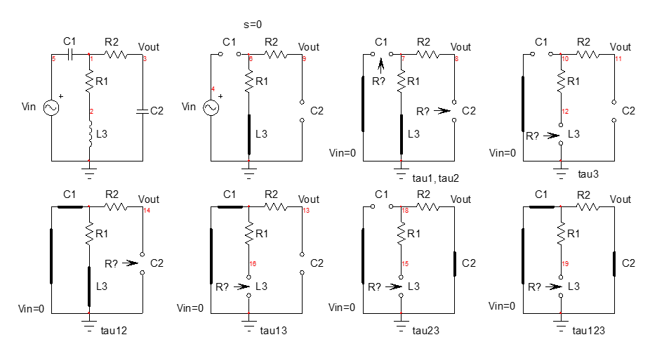
When I see the amount of lines thrown on the blank page by the OP as an attempt to derive this 3rd-order transfer function, I think it is about time time that fast analytical circuits techniques or FACTs are taught in universities. The principle is simple and, very often, works with inspection: just look at the circuit to infer the time constants without writing a single line of algebra. The exercise consists of determining the resistance \$R\$ offered by each energy-storing element when the circuit is observed with a zeroed excitation or with a nulled response. Once you have the \$R\$, you can form a time constant expressed as \$\tau=RC\$ or \$\tau=\frac{L}{R}\$.

So we start with a bunch of small sketches to determine the natural time constants of this linear circuit. We reduce the excitation to zero volt (the input source is replaced by a short circuit) and you "look" through the energy-storing element temporarily disconnected from the circuit to find the resistance \$R\$ driving that element:

enter image description here

As you can see, you just inspect the drawing to see, in your head, what resistance the terminals in question offer (where the arrow points). And if you make a mistake, it is easy and fast to come back to the circuit and correct the resistance \$R\$ you mistakenly determined.

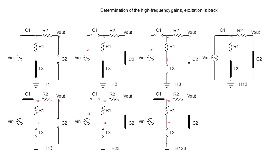
For the zeroes, you can do what is a called a null double injection (NDI) but I often prefer for the passive case, to determine high-frequency gains: the source is back in place and you inspect the circuit to determine what the gains are when energy-storing elements are alternately placed in their high-frequency state:

enter image description here

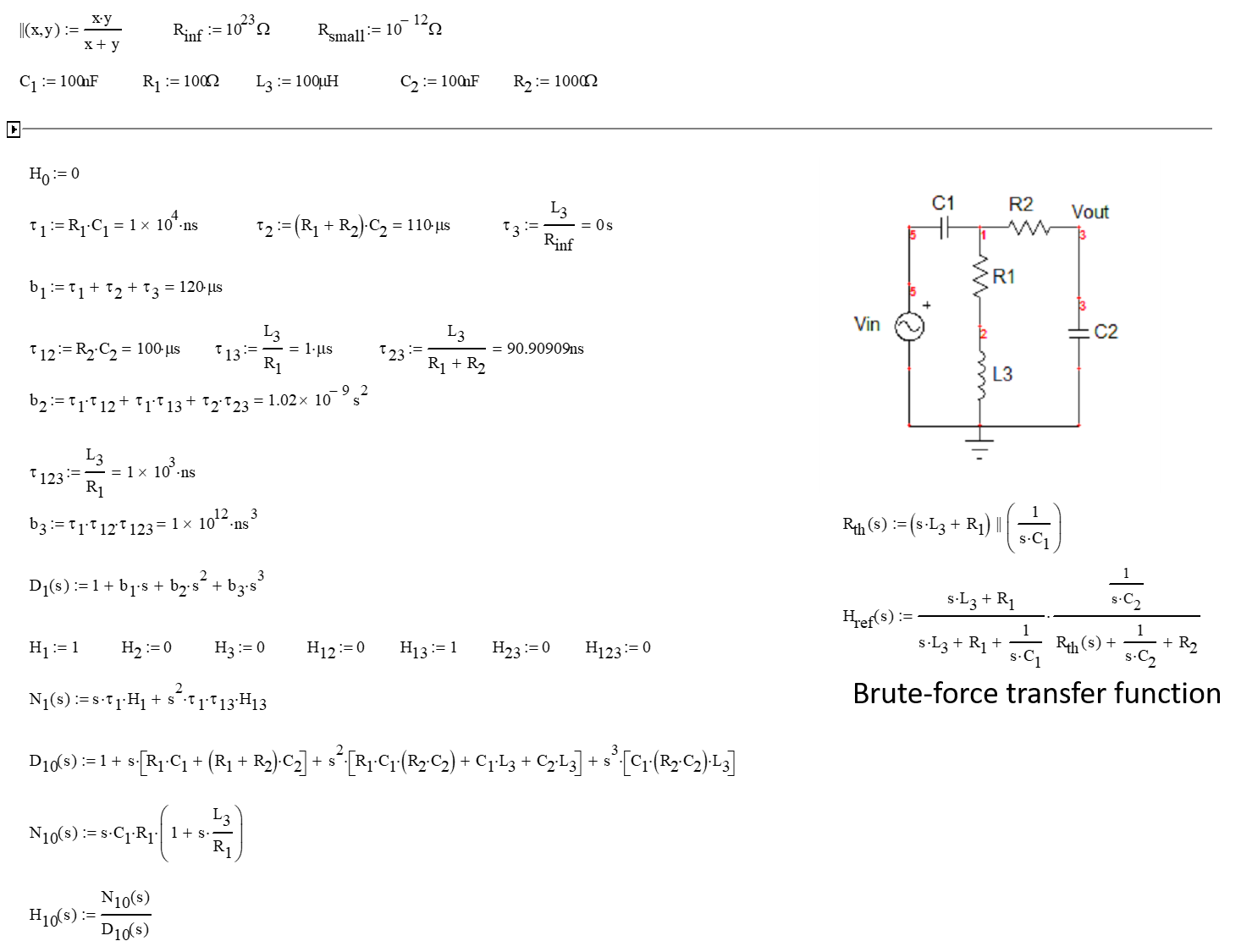
You can see how easy it is! When you have all these elements on hand, you assemble them in a Mathcad sheet which a) will check homogeneity of the formulas and b) will let you compare the response obtained by the FACTs and that delivered by the brute-force approach (Thévenin in this case):

enter image description here

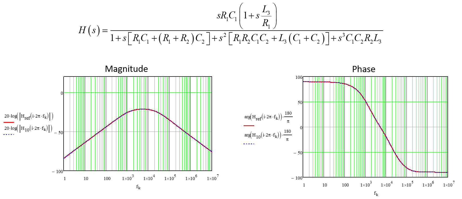
Then you can plot the magnitude and phase while comparing the two responses in similar plots. They perfectly match as shown below:

enter image description here

You can see how easy the FACTs are compared to the classical KVL and KCL methods. You apply the divide-and-conquer strategy promoted by Dr. Middlebrook and solve your circuit step-by-step with the ability to come back and solve an intermediate wrong result. There is no way you can do that with the brute-force approach.

Acquiring the FACTs skill is simple and you can start with 1st-order circuits as shown in the APEC seminar I taught in 2016. Then, for an in-depth description of the method up to the order \$N\$, you can have a look at the book I published on the subject.

\$\endgroup\$
3
  • \$\begingroup\$ I'm not comfortable teaching these. So I'm very glad to see the moments offered when you show up like this. Thanks. \$\endgroup\$
    – jonk
    Commented Apr 11, 2021 at 2:36
  • \$\begingroup\$ @jonk, I am glad if my contribution helps. I am sure that if you try the FACTs you won't come back to the classical approach ^_^ Cheers! \$\endgroup\$ Commented Apr 11, 2021 at 8:19
  • \$\begingroup\$ I've tried them. Just not yet enough. But enough to know I want to try them more. I just have so much ease and certainty with other methods and sufficient imagination that I can "find" the time constants directly in the equations from inspection (or else easily from standard approaches I otherwise use.) Those things I've done and tested over and over. I just need to find the enjoyable time for FACTs and then to compare my mindset for both, later. (I did get your 2016 book and I've read some. Just haven't had time to do it justice yet.) \$\endgroup\$
    – jonk
    Commented Apr 11, 2021 at 16:12

Your Answer

By clicking “Post Your Answer”, you agree to our terms of service and acknowledge you have read our privacy policy.

Not the answer you're looking for? Browse other questions tagged or ask your own question.