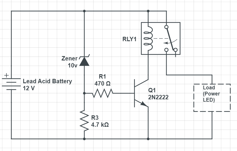
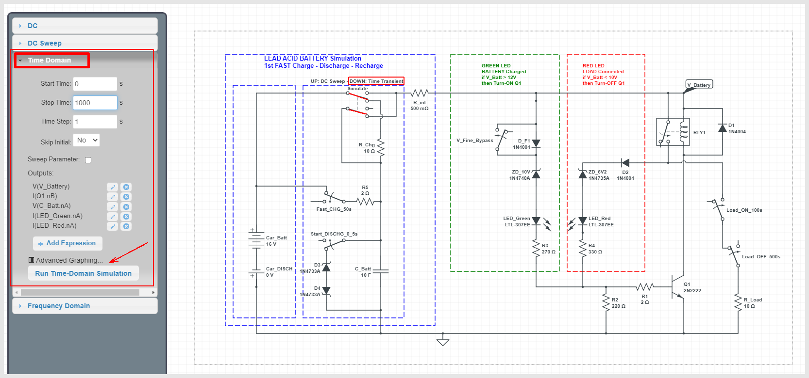
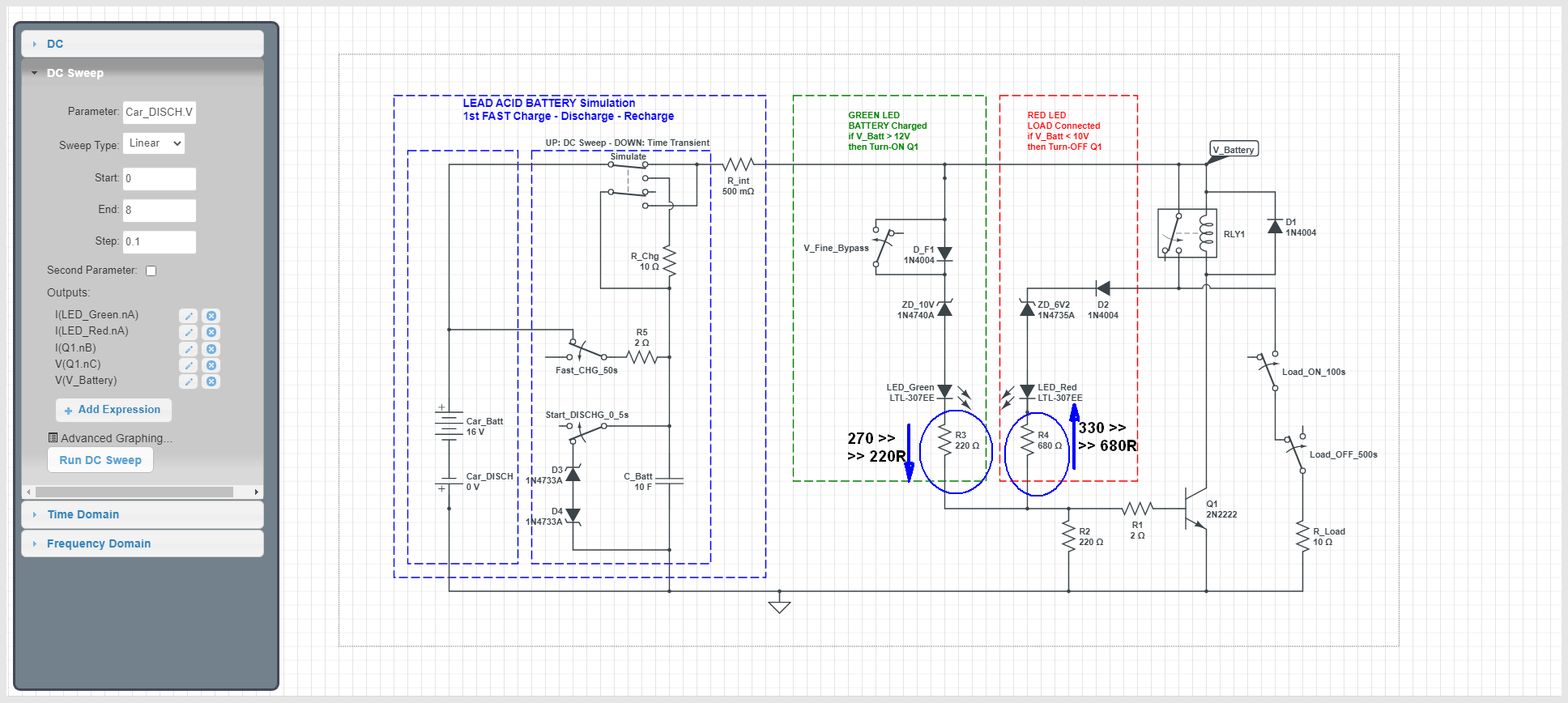
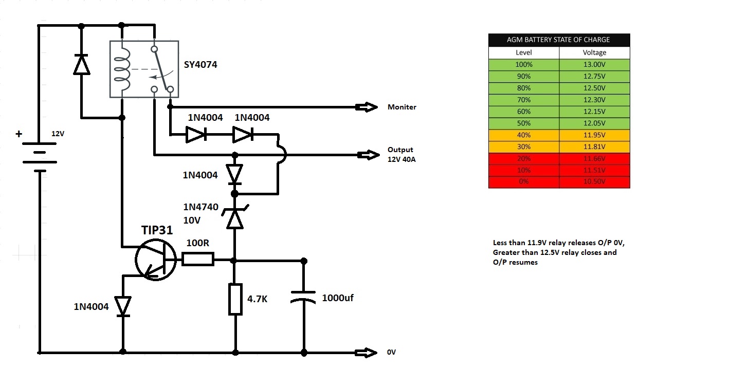
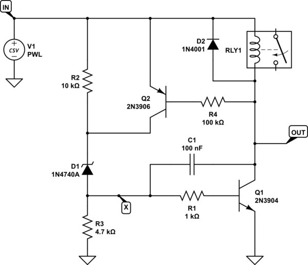
I've created a circuit to protect my lead-acid battery from over-discharging. I used the following circuit diagram.
Over-discharge protection circuit for a lead acid battery:
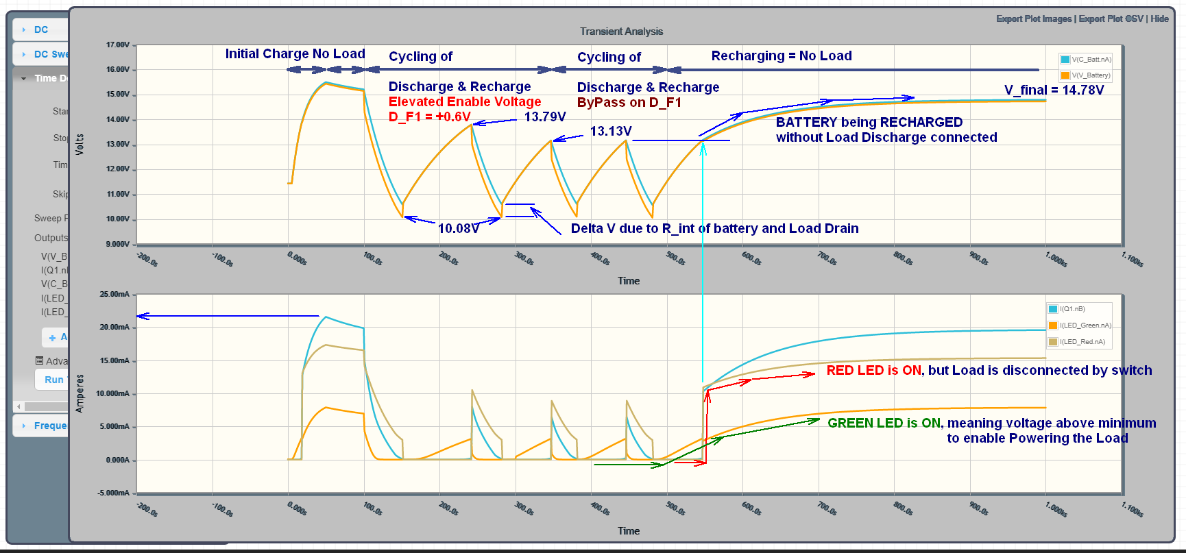
For understandable reasons, the circuit is oscillating if I connect the battery to a load through this protection circuit and the battery voltage reaches the approx. 10.6 V threshold. When oscillating, the relay disconnects and reconnects repeatedly very fast, making a sharp noise, and the load LED flickers.
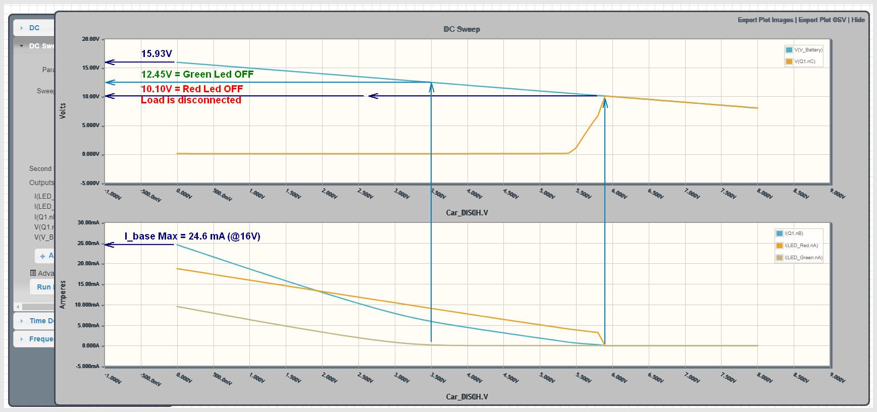
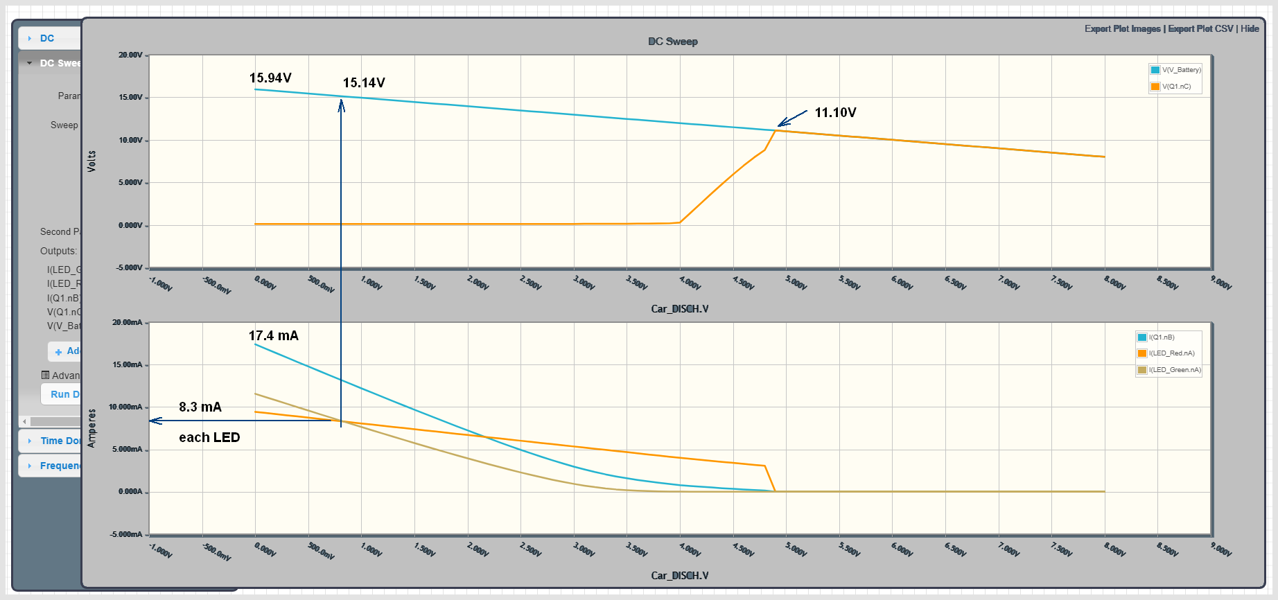
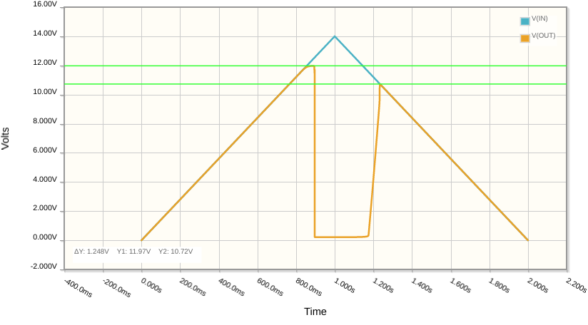
When I tested the circuit using my bench power supply, I didn't see the circuit oscillate as the voltage goes below threshold. It cuts off the supply to the load, as intended.
When on the battery, I guess this is happening because as soon as the relay disconnects, due to absence of load, the battery voltage rises very slightly above the threshold, the Zener breaks down and the relay connects back. This keeps happening in a loop.
I know that making an over-discharge protection circuit is quite easy with appropriate protection ICs, but I am looking for a simpler solution without using any special-purpose IC.
What change in the circuit can make it work the way I am expecting it to?
Note: my load may consume a very large current, so I do not want the load to run through a transistor or MOSFET if possible but use a relay instead.
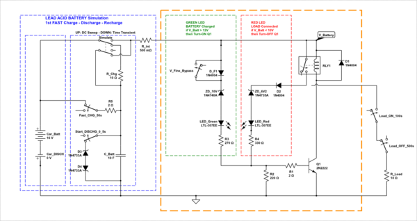
I learnt that a Schmitt trigger is the solution, but I'm really a newbie hobbyist. I understand the basics of the Schmitt trigger but can't really configure the circuit with appropriate values so that it cuts off at 10.5 V and doesn't turn on until 12 V. Can you please help me with the circuit?

