0
\$\begingroup\$

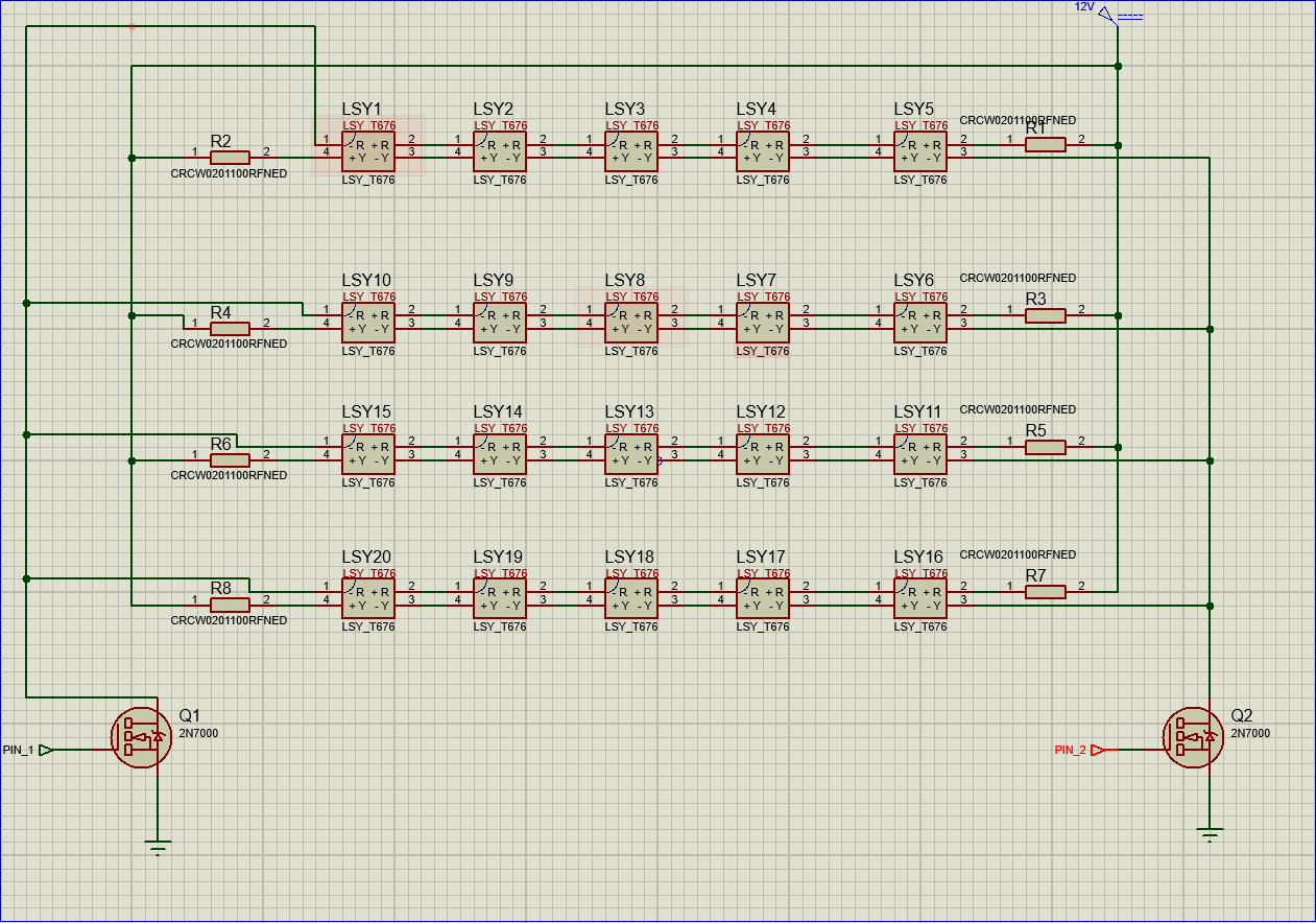
I want to "develop" a project with some bi-color LEDs (OSRAM LSY-T676.) I have made (after some tutorials) my own component because it was not included in Proteus 8 library. Source which is used is a car battery (12V), the LEDs have a forward voltage of 2V for both colors and a forward current of 20mA (nominal.) I need to use twenty of these LEDs, so I made four groups of five LEDs (10V forward voltage.) After basic calculation, a 100ohm resistor is needed to obtain the correct current.

I'm want to control the LEDs with a PIC12F675 microcontroller (as I read in datasheet: current 25mA and Vdd-0.7V => 5-0.7= 4.3V output if Vdd will be 5V as I want.) The idea was to use a 2N7000 N-channel MOSFET (Vgs(th) =2.1V Id=115mA) but I'm not really sure if I interpreted the data for the microcontroller and MOSFET correctly. Could you, please, correct me, if somethingbis wrong? My questions are:

  1. What is the maximum frequency for PWM (I want to control LEDs via PWM.)
  2. How should I calculate the base resistor?
  3. Do I need a parallel capacitor? (I saw some examples on forums.) If it is needed, how can I calculate the value?
  4. What is the influence of RDS(on)? (As I understood is one of the most important characteristic)

My circuit

2n700-datasheet maximum current drain-source 2n700-datasheet voltage to "Turn On" MOSFET PIC12F675- datasheet nominal voltage for OUTPUT PIN

\$\endgroup\$
7
  • \$\begingroup\$ Where did you get 25mA current for PIC? Also, FETs don't have a terminal called base, it's called gate. \$\endgroup\$
    – Justme
    Commented Mar 16, 2023 at 20:22
  • \$\begingroup\$ Hello, and thank you for support. \$\endgroup\$
    – SkePsis
    Commented Mar 17, 2023 at 5:31
  • \$\begingroup\$ I`m sorry for previous comment (I can't edit now). I called base due to speed writing. I will attach a picture with spec from datasheet of PIC12F675 ibb.co/LNry20q. Maybe I don't understood correct. Please correct me if I am wrong. \$\endgroup\$
    – SkePsis
    Commented Mar 17, 2023 at 6:07
  • \$\begingroup\$ Yes, it says 25mA, but because you copy-pasted it as picture and blanked out the rest to give any context, you don't know what it means. A link to data sheet with page number or section would have been better providing the info with less effort to provide it. \$\endgroup\$
    – Justme
    Commented Mar 17, 2023 at 6:15
  • 1
    \$\begingroup\$ This was not about LED data sheet, it was about the PIC12F data sheet you quoted. I can go and google for it, but how do I know we are reading the same or different data sheet. It is important to have the exact same data sheet, not a different version of it, which may be different. Please provide a link to the data sheet if you want help understanding it. \$\endgroup\$
    – Justme
    Commented Mar 17, 2023 at 9:31

2 Answers 2

1
\$\begingroup\$

You control the MOSFET with voltage, so you do not need a resistor for the gate. The 5V from the I/O-pin are going directly to the Gate and switch the MOSFET on.

If you want to use two MOSFETs in parallel to reduce the Rds_on, then you should add 10 ohm resistor between the gate and the I/O-pin.

You should measure the voltage drop over the LED at the maximum current and then you can calculate the resistor value. It is better to use the lowest current that works for you. The 30mA is the absolute maximum value. If you use a lower current, then the endurance of this LED is longer.

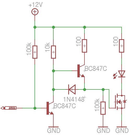
Inverted driver for the MOSFET: Inverted MosFET driver

For stability of the voltage, it is useful to use a 12V low drop voltage regulator.

If the car should drive and the battery is connected to the car, then you need something for the safety. You have high voltage peaks in a car, negative voltage and a lot of noise. You need protection diodes and a filter.

\$\endgroup\$
7
  • \$\begingroup\$ According to data sheet, 20mA is the rated current and 30mA is the absolute maximum. \$\endgroup\$
    – Justme
    Commented Mar 16, 2023 at 20:30
  • 1
    \$\begingroup\$ Your LED DO NOT have a forward voltage of 2.0V, some of them might be 2.0V and others could be 1.8V to 2.4V. If they are all 1.8V and the battery is charging at 14V then the current in five in series is 50mA and they will soon burn out. \$\endgroup\$
    – Audioguru
    Commented Mar 17, 2023 at 0:43
  • \$\begingroup\$ @Audioguru - If the LED-chip is from good quality and was not created in a Chinese backyard, then the forward voltage is the same. If there are Impurities inside of the chip, then this creates a parallel resistor between the layer of the chip. There you have the effect that there is a current flow through the LED, but she do not lit up. This parallel resistor on the chip can be very small, maybe 120 Ohm, then you need a lot of current till the LED start to glow. I think Osram do not sell this type of junk. \$\endgroup\$
    – MikroPower
    Commented Mar 17, 2023 at 1:05
  • \$\begingroup\$ @MikroPower The LED forward voltage is a function of temperature and manufacturing tolerances. If Osram data sheet says you get 20mA at 1.8V to 2.4V range, and does not sell them as voltage binned, then that's the range you get. It's not junk. \$\endgroup\$
    – Justme
    Commented Mar 17, 2023 at 5:44
  • 1
    \$\begingroup\$ @SkePsis - This circuit is a MOSFET driver for PWM. I use it up to 100kHz. \$\endgroup\$
    – MikroPower
    Commented Mar 17, 2023 at 10:41
1
\$\begingroup\$

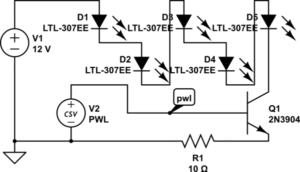
You need to take into account that the car battery voltage can vary from 13.8 volts (fully charged) to about 11 volts (mostly depleted). So to be sure that the current stays below 20 mA, a resistor of 3.8/20 = 190 ohms would be needed. A better way to control LED current might be a circuit as follows:

schematic

simulate this circuit – Schematic created using CircuitLab

Voltages

LED current

The voltage ramp (pwl) could be replaced with a variable duty cycle PWM, and a voltage divider could be added to the base drive such that a 5V PWM will drive a maximum of 20-25 mA at 100% duty cycle. The LED current is not quite a linear function of the drive voltage, but you could monitor the voltage on R1 and adjust as needed. An op-amp could be used for a very linear I/R LED function.

(edit) The PWL (piece-wise linear) voltage source in this case is a linear ramp starting at 600 mV and ending with 1 V at 300 ms. A PWM signal will also work, with peak current limited by R1 and the Vbe of Q1.

A MOSFET should also work, with the ramp starting at Vgs(thresh), so the starting point will be higher. Stability should be OK with either device. There will be a temperature coefficient in both cases.

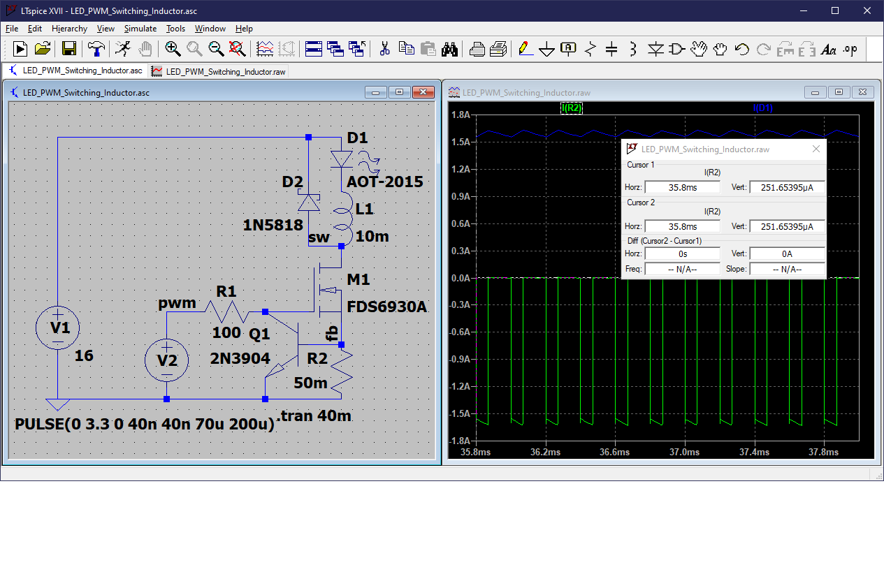
Using PWM will probably be most stable, although the peak current will vary. You could also add an inductor in series with the LED string, and a flyback diode connected in anti-parallel. This can essentially eliminate ripple inherent with PWM. The current limiter circuit using Q1 is optional, but might protect against destructive overcurrent in case of duty cycle too high.

PWM LED drive with inductor

\$\endgroup\$
1
  • \$\begingroup\$ Hello and thank you! PWL (V2) meaning PWM source? Is a better idea to use BJT instead of MOSFET? Will be, let's say "more stabile"? \$\endgroup\$
    – SkePsis
    Commented Mar 17, 2023 at 6:52

Your Answer

By clicking “Post Your Answer”, you agree to our terms of service and acknowledge you have read our privacy policy.

Not the answer you're looking for? Browse other questions tagged or ask your own question.