added 9 characters in body
Source Link
Spehro 'speff' Pefhany
  • 422.6k
  • 23
  • 352
  • 950

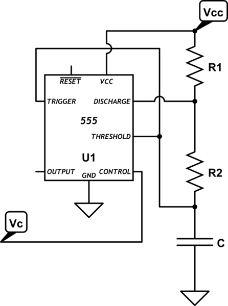
schematic

simulate this circuit – Schematic created using CircuitLab

The time when the output is high is \$ T_H = \tau_1ln(1- \$ \$V_C\over 2Vdd - Vc \$)

(it charges from \$V_C/2\$ to \$V_C\$)

The time when the output is low is \$T_L = \tau_2 ln(2)\$

(it discharges from \$V_C\$ to \$V_C/2\$)

frequency is f = \$1\over T_H + T_L\$

Where

\$ \tau_1 = (R1 + R2)\cdot C\$

\$ \tau_2 = (R2) \cdot C\$

The above ignores propagation delays and saturation voltages, so it's more accurate for low frequencies, fairly high resistance values, and a CMOS 555.

Here is an example plot with R1 = 1K, R2 = 10K, C = 10uF10\$\mu\$F, Vcc = 10V and Vc\$V_C\$ varied from 0.5V to 9.5V.
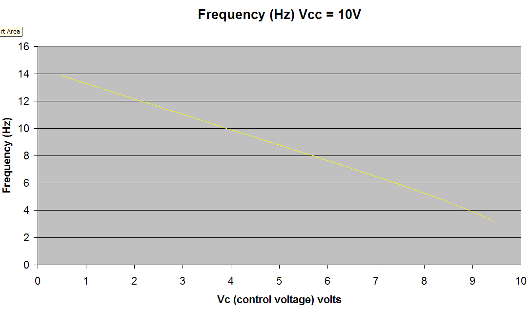
enter image description here

schematic

simulate this circuit – Schematic created using CircuitLab

The time when the output is high is \$ T_H = \tau_1ln(1- \$ \$V_C\over 2Vdd - Vc \$)

(it charges from \$V_C/2\$ to \$V_C\$)

The time when the output is low is \$T_L = \tau_2 ln(2)\$

(it discharges from \$V_C\$ to \$V_C/2\$)

frequency is f = \$1\over T_H + T_L\$

Where

\$ \tau_1 = (R1 + R2)\cdot C\$

\$ \tau_2 = (R2) \cdot C\$

The above ignores propagation delays and saturation voltages, so it's more accurate for low frequencies, fairly high resistance values, and a CMOS 555.

Here is an example plot with R1 = 1K, R2 = 10K, C = 10uF, Vcc = 10V and Vc varied from 0.5V to 9.5V.

enter image description here

schematic

simulate this circuit – Schematic created using CircuitLab

The time when the output is high is \$ T_H = \tau_1ln(1- \$ \$V_C\over 2Vdd - Vc \$)

(it charges from \$V_C/2\$ to \$V_C\$)

The time when the output is low is \$T_L = \tau_2 ln(2)\$

(it discharges from \$V_C\$ to \$V_C/2\$)

frequency is f = \$1\over T_H + T_L\$

Where

\$ \tau_1 = (R1 + R2)\cdot C\$

\$ \tau_2 = (R2) \cdot C\$

The above ignores propagation delays and saturation voltages, so it's more accurate for low frequencies, fairly high resistance values, and a CMOS 555.

Here is an example plot with R1 = 1K, R2 = 10K, C = 10\$\mu\$F, Vcc = 10V and \$V_C\$ varied from 0.5V to 9.5V.

enter image description here

added 188 characters in body
Source Link
Spehro 'speff' Pefhany
  • 422.6k
  • 23
  • 352
  • 950

schematic

simulate this circuit – Schematic created using CircuitLab

The time when the output is high is \$ T_H = \tau_1ln(1- \$ \$V_C\over 2Vdd - Vc \$)

(it charges from \$V_C/2\$ to \$V_C\$)

The time when the output is low is \$T_L = \tau_2 ln(2)\$

(it discharges from \$V_C\$ to \$V_C/2\$)

frequency is f = \$1\over T_H + T_L\$

Where

\$ \tau_1 = (R1 + R2)\cdot C\$

\$ \tau_2 = (R2) \cdot C\$

The above ignores propagation delays and saturation voltages, so it's more accurate for low frequencies, fairly high resistance values, and a CMOS 555.

Here is an example plot with R1 = 1K, R2 = 10K, C = 10uF, Vcc = 10V and Vc varied from 0.5V to 9.5V.

enter image description here

schematic

simulate this circuit – Schematic created using CircuitLab

The time when the output is high is \$ T_H = \tau_1ln(1- \$ \$V_C\over 2Vdd - Vc \$)

(it charges from \$V_C/2\$ to \$V_C\$)

The time when the output is low is \$T_L = \tau_2 ln(2)\$

(it discharges from \$V_C\$ to \$V_C/2\$)

frequency is f = \$1\over T_H + T_L\$

Where

\$ \tau_1 = (R1 + R2)\cdot C\$

\$ \tau_2 = (R2) \cdot C\$

The above ignores propagation delays and saturation voltages, so it's more accurate for low frequencies, fairly high resistance values, and a CMOS 555.

Here is an example plot with R1 = 1K, R2 = 10K, C = 10uF, Vcc = 10V and Vc varied from 0.5V to 9.5V.

enter image description here

Source Link
Spehro 'speff' Pefhany
  • 422.6k
  • 23
  • 352
  • 950

schematic

simulate this circuit – Schematic created using CircuitLab

The time when the output is high is \$ T_H = \tau_1ln(1- \$ \$V_C\over 2Vdd - Vc \$)

(it charges from \$V_C/2\$ to \$V_C\$)

The time when the output is low is \$T_L = \tau_2 ln(2)\$

(it discharges from \$V_C\$ to \$V_C/2\$)

frequency is f = \$1\over T_H + T_L\$

Where

\$ \tau_1 = (R1 + R2)\cdot C\$

\$ \tau_2 = (R2) \cdot C\$

The above ignores propagation delays and saturation voltages, so it's more accurate for low frequencies, fairly high resistance values, and a CMOS 555.