added 514 characters in body
Source Link
user38637
user38637

Edit Looks like it works fine except for excess cable capacitance for 5k pullup. You might try twisted pair or shorter cable or add another 10k or 5k worse case for pullup to 5V echoes to all including the last one using negative edges indicate time of arrival of echoes. Use the velocity of sound in air for distance and width of negative pulse to mean size of object. Calibrate using stepped gap with a rigid block of known size for time interval and compare with computed delay results. Record sensitivity vs off axis at same radius to map beam pattern.

Endedit

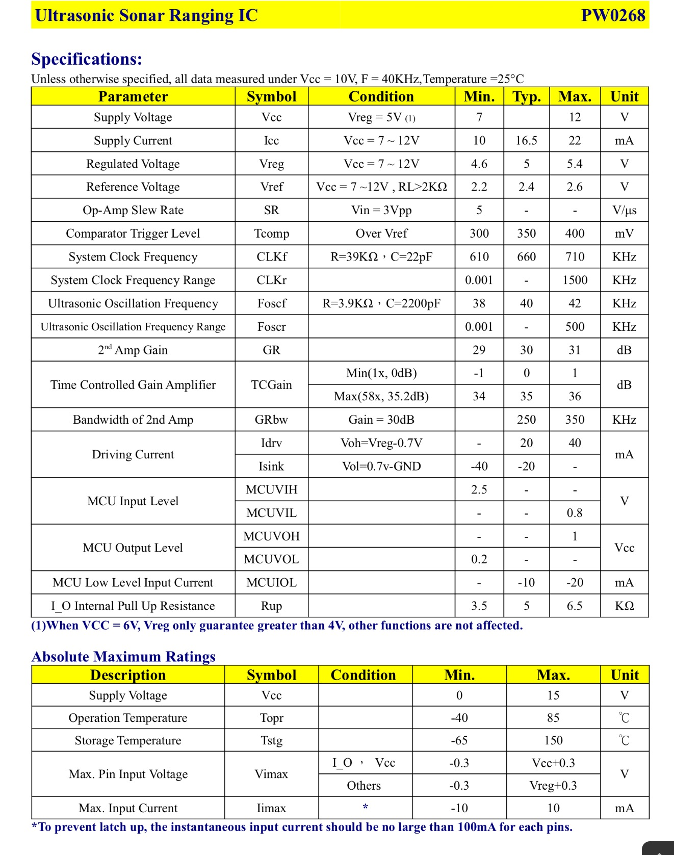
Critical to all R&D is comparing results to specifications.

If you can manage to verify the table of every spec, starting from voltage , current, etc .. All the way down in a checklist. Then draw a thumbnail scope reading of each pin using short gnd leads on 1 page and then compare with spec...

Be wary that the chip uses a ramped voltage controlled gain to compensate for attenuation versus time delay due to inverse squared loss. You can verify he gain by "back driving" from another speaker + generator at a very low level to determine the threshold of gain without having to rig echoes at different distances.

Then, you should be able to pinpoint the issue or at least ask a better question!!

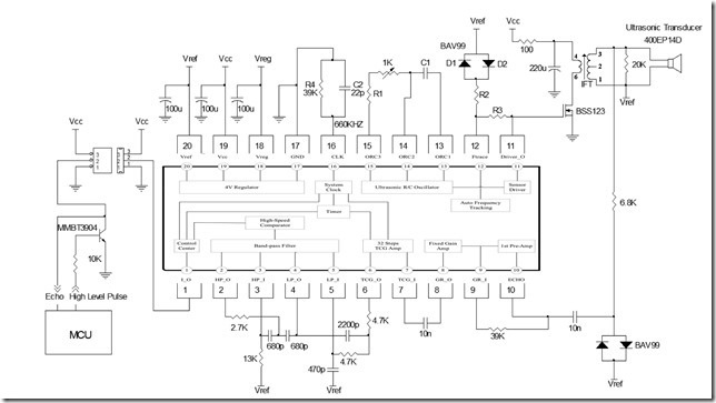
Read the Specs may require experience, but start with the analog inputs and outputs which get amplified filtered and detected into pulse shapes which can then be sliced into logic levels with the output transistor Vbe threshold. Draw the waveforms as thumbnails around the diagram from the data sheet

1: http://www.prowave.com.tw/pdf/sonaric.pdf, then compare with test results. record Vdc otherwise.

Professionals do this in their sleep. You have to start on paper.

Here is a start for you, where I cut and paste the inside to the outside circuit. Someone can add arrows for direction the signals take here, which seems to be clockwise in his case.
enter image description here

enter image description here

Critical to all R&D is comparing results to specifications.

If you can manage to verify the table of every spec, starting from voltage , current, etc .. All the way down in a checklist. Then draw a thumbnail scope reading of each pin using short gnd leads on 1 page and then compare with spec...

Be wary that the chip uses a ramped voltage controlled gain to compensate for attenuation versus time delay due to inverse squared loss. You can verify he gain by "back driving" from another speaker + generator at a very low level to determine the threshold of gain without having to rig echoes at different distances.

Then, you should be able to pinpoint the issue or at least ask a better question!!

Read the Specs may require experience, but start with the analog inputs and outputs which get amplified filtered and detected into pulse shapes which can then be sliced into logic levels with the output transistor Vbe threshold. Draw the waveforms as thumbnails around the diagram from the data sheet

1: http://www.prowave.com.tw/pdf/sonaric.pdf, then compare with test results. record Vdc otherwise.

Professionals do this in their sleep. You have to start on paper.

Here is a start for you, where I cut and paste the inside to the outside circuit. Someone can add arrows for direction the signals take here, which seems to be clockwise in his case.

enter image description here

enter image description here

Edit Looks like it works fine except for excess cable capacitance for 5k pullup. You might try twisted pair or shorter cable or add another 10k or 5k worse case for pullup to 5V echoes to all including the last one using negative edges indicate time of arrival of echoes. Use the velocity of sound in air for distance and width of negative pulse to mean size of object. Calibrate using stepped gap with a rigid block of known size for time interval and compare with computed delay results. Record sensitivity vs off axis at same radius to map beam pattern.

Endedit

Critical to all R&D is comparing results to specifications.

If you can manage to verify the table of every spec, starting from voltage , current, etc .. All the way down in a checklist. Then draw a thumbnail scope reading of each pin using short gnd leads on 1 page and then compare with spec...

Be wary that the chip uses a ramped voltage controlled gain to compensate for attenuation versus time delay due to inverse squared loss. You can verify he gain by "back driving" from another speaker + generator at a very low level to determine the threshold of gain without having to rig echoes at different distances.

Then, you should be able to pinpoint the issue or at least ask a better question!!

Read the Specs may require experience, but start with the analog inputs and outputs which get amplified filtered and detected into pulse shapes which can then be sliced into logic levels with the output transistor Vbe threshold. Draw the waveforms as thumbnails around the diagram from the data sheet

1: http://www.prowave.com.tw/pdf/sonaric.pdf, then compare with test results. record Vdc otherwise.

Professionals do this in their sleep. You have to start on paper.

Here is a start for you, where I cut and paste the inside to the outside circuit. Someone can add arrows for direction the signals take here, which seems to be clockwise in his case.

enter image description here

enter image description here

plenty of specs to work with
Source Link
user38637
user38637

Critical to all R&D is comparing results to specifications.specifications.

If you can manage to verify the table of every spec, starting from voltage , current, etc .. All the way down in a checklist. Then draw a thumbnail scope reading of each pin using short gnd leads on 1 page and then compare with spec...

Be wary that the chip uses a ramped voltage controlled gain to compensate for attenuation versus time delay due to inverse squared loss. You can verify he gain by "back driving" from another speaker + generator at a very low level to determine the threshold of gain without having to rig echoes at different distances.

Then, you should be able to pinpoint the issue or at least ask a better question!!

Read the Specs may require experience, but start with the analog inputs and outputs which get amplified filtered and detected into pulse shapes which can then be sliced into logic levels with the output transistor Vbe threshold. Draw the waveforms as thumbnails around the diagram from the data sheet

1: http://www.prowave.com.tw/pdf/sonaric.pdf, then compare with test results. record Vdc otherwise.

Professionals do this in their sleep. You have to start on paper.

Here is a start for you, where I cut and paste the inside to the outside circuit. Someone can add arrows for direction the signals take here, which seems to be clockwise in his case.

enter image description here

enter image description here

Critical to all R&D is comparing results to specifications.

If you can manage to verify the table of every spec, starting from voltage , current, etc .. All the way down in a checklist. Then draw a thumbnail scope reading of each pin using short gnd leads on 1 page and then compare with spec...

Be wary that the chip uses a ramped voltage controlled gain to compensate for attenuation versus time delay due to inverse squared loss. You can verify he gain by "back driving" from another speaker + generator at a very low level to determine the threshold of gain without having to rig echoes at different distances.

Then, you should be able to pinpoint the issue or at least ask a better question!!

Read the Specs may require experience, but start with the analog inputs and outputs which get amplified filtered and detected into pulse shapes which can then be sliced into logic levels with the output transistor Vbe threshold. Draw the waveforms as thumbnails around the diagram from the data sheet

1: http://www.prowave.com.tw/pdf/sonaric.pdf, then compare with test results. record Vdc otherwise.

Professionals do this in their sleep. You have to start on paper.

Here is a start for you, where I cut and paste the inside to the outside circuit. Someone can add arrows for direction the signals take here, which seems to be clockwise in his case.

enter image description here

enter image description here

Source Link
user38637
user38637

Critical to all R&D is comparing results to specifications.

If you can manage to verify the table of every spec, starting from voltage , current, etc .. All the way down in a checklist. Then draw a thumbnail scope reading of each pin using short gnd leads on 1 page and then compare with spec...

Be wary that the chip uses a ramped voltage controlled gain to compensate for attenuation versus time delay due to inverse squared loss. You can verify he gain by "back driving" from another speaker + generator at a very low level to determine the threshold of gain without having to rig echoes at different distances.

Then, you should be able to pinpoint the issue or at least ask a better question!!