added 1682 characters in body
Source Link

I've been lately reading about capacitors, but all the formulae needs of resistance to work. However, there might be cases where resistors aren't present on the charge or discharge paths. Consider the following circuit:
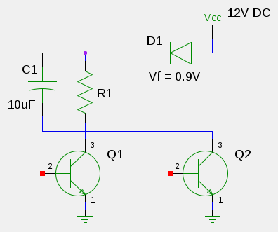
capacitor charge/discharge

Initiallly, both Q1 and Q2 are closed, and the capacitor C1 is discharged.

Then Q2 opens (the capacitor is charged through the diode D1) and then closes.

Q1 opens, the capacitor discharges through it and R1 to ground.

What I want to is calculate the time needed for C1 to charge and discharge, so that I can adjust it to my needs.

I think I'm doing the discharge part right (not sure because of the presence of Q1 there, though).

So my question is, can somebody solve both parts for me on the above circuit so I can get to know how it's done? An explanation would also be useful (i.e.: what resistance value to use when charging in cases like these, as the is no resistor?, does Q1 presence actually matters when calculating discharge times?).

Edit:

Thanks a lot guys. I just drew that circuit on a moment, as I'm myself done a mess with all the capacitor theory and I didn't even express myself properly (with closed I meant: non-conducting, and with open I meant: conducting).

This time I'll put the original image, as I should have done in first place:
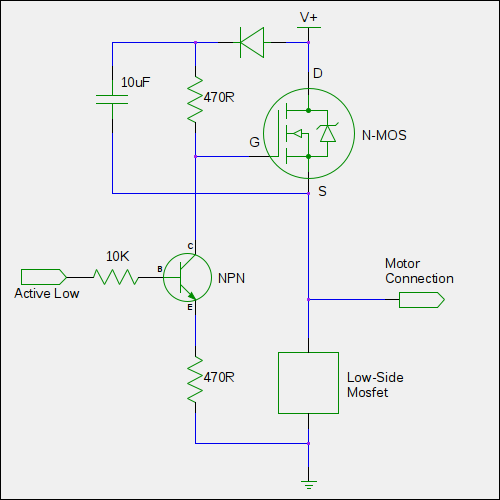
enter image description here

This is a basic discrete half-bridge driver for blcd motors (nmos-based), and what I'm trying is to calculate minimum and maximum on-off times that 10uF capacitor could provide, to then, change it according to my needs, if at all needed.

As some of you said and I guessed, the transistor shows some resistance from collector to emitter while coducting, that's ok.

But I'm still not understanding what resistance should I use in the formulae when calculating the charging part if there's no resistor present (npn conducting, low side nmos conducting enough time for the capacitor to charge up, to then let the npn have a rest so the capacitor discharges on to the nmos gate through the resistor, turning it on).

Perhaps it's just a dumb question, I even got a bit stressed looking on the internet for an explanation/tutorial of a capacitor charging/discharging without a resistor, in the hope of getting to understand all this (though I know a resistor is needed in a real circuit to limit the current).

All I can see from the second circuit posted is that the capacitor charges up quicker than it discharges, but can't do the maths because on the charging path there's no resistor, but the diode, so in cases like this, should I use some small value or what?

I've been lately reading about capacitors, but all the formulae needs of resistance to work. However, there might be cases where resistors aren't present on the charge or discharge paths. Consider the following circuit:

capacitor charge/discharge

Initiallly, both Q1 and Q2 are closed, and the capacitor C1 is discharged.

Then Q2 opens (the capacitor is charged through the diode D1) and then closes.

Q1 opens, the capacitor discharges through it and R1 to ground.

What I want to is calculate the time needed for C1 to charge and discharge, so that I can adjust it to my needs.

I think I'm doing the discharge part right (not sure because of the presence of Q1 there, though).

So my question is, can somebody solve both parts for me on the above circuit so I can get to know how it's done? An explanation would also be useful (i.e.: what resistance value to use when charging in cases like these, as the is no resistor?, does Q1 presence actually matters when calculating discharge times?).

Edit:

Thanks a lot guys. I just drew that circuit on a moment, as I'm myself done a mess with all the capacitor theory and I didn't even express myself properly (with closed I meant: non-conducting, and with open I meant: conducting).

This time I'll put the original image, as I should have done in first place:

enter image description here

This is a basic discrete half-bridge driver for blcd motors (nmos-based), and what I'm trying is to calculate minimum and maximum on-off times that 10uF capacitor could provide, to then, change it according to my needs, if at all needed.

As some of you said and I guessed, the transistor shows some resistance from collector to emitter while coducting, that's ok.

But I'm still not understanding what resistance should I use in the formulae when calculating the charging part if there's no resistor present (npn conducting, low side nmos conducting enough time for the capacitor to charge up, to then let the npn have a rest so the capacitor discharges on to the nmos gate through the resistor, turning it on).

Perhaps it's just a dumb question, I even got a bit stressed looking on the internet for an explanation/tutorial of a capacitor charging/discharging without a resistor, in the hope of getting to understand all this (though I know a resistor is needed in a real circuit to limit the current).

All I can see from the second circuit posted is that the capacitor charges up quicker than it discharges, but can't do the maths because on the charging path there's no resistor, but the diode, so in cases like this, should I use some small value or what?

Source Link

A path for capacitor's charging, and another for discharging it

I've been lately reading about capacitors, but all the formulae needs of resistance to work. However, there might be cases where resistors aren't present on the charge or discharge paths. Consider the following circuit:

capacitor charge/discharge

Initiallly, both Q1 and Q2 are closed, and the capacitor C1 is discharged.

Then Q2 opens (the capacitor is charged through the diode D1) and then closes.

Q1 opens, the capacitor discharges through it and R1 to ground.

What I want to is calculate the time needed for C1 to charge and discharge, so that I can adjust it to my needs.

I think I'm doing the discharge part right (not sure because of the presence of Q1 there, though).

So my question is, can somebody solve both parts for me on the above circuit so I can get to know how it's done? An explanation would also be useful (i.e.: what resistance value to use when charging in cases like these, as the is no resistor?, does Q1 presence actually matters when calculating discharge times?).