replaced http://electronics.stackexchange.com/ with https://electronics.stackexchange.com/
Source Link

Regarding the chosen answer for: How does this OP-AMP non-inverting amplifier work?How does this OP-AMP non-inverting amplifier work?

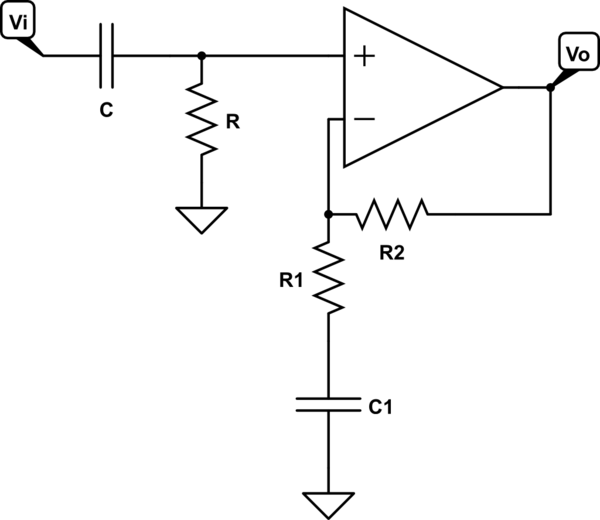
The following circuit is given, and it says that $$F_c = \frac{1}{2\pi R_1C_1}$$
schematic

simulate this circuit – Schematic created using CircuitLab

However, this doesn't seem right to me, even though I have found the same example and formula elsewhere on the web (e.g., "Non-inverting amplifier – alternative" at http://stompville.co.uk/?p=470).

To me it doesn't take into account the value of the op amp feedback resistor (\$R_2\$ in the sketch above).

Would the cut-off frequency not be based upon (\$R_1+R_2\$)? If not, why not?

My point is that the only way the capacitor can charge or discharge is through the output of the op-amp, so surely the feedback resistor is also critical?

Regarding the chosen answer for: How does this OP-AMP non-inverting amplifier work?

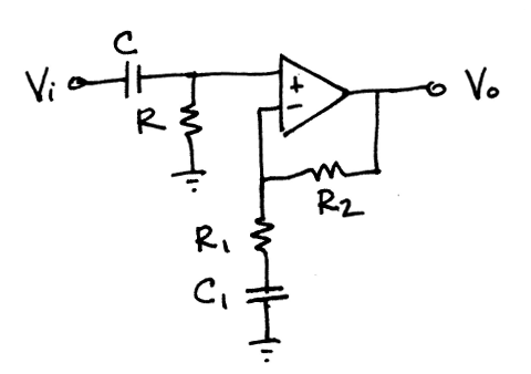
The following circuit is given, and it says that $$F_c = \frac{1}{2\pi R_1C_1}$$


Fig1schematic

simulate this circuit – Schematic created using CircuitLab

However, this doesn't seem right to me, even though I have found the same example and formula elsewhere on the web (e.g., "Non-inverting amplifier – alternative" at http://stompville.co.uk/?p=470). To

To me it doesn't take into account the value of the op amp feedback resistor (\$R_2\$ in the sketch above). Would

Would the cut-off frequency not be based upon (\$R_1+R_2\$)? If not, why not? My

My point is that the only way the capacitor can charge or discharge is through the output of the op-amp, so surely the feedback resistor is also critical?

Regarding the chosen answer for: How does this OP-AMP non-inverting amplifier work?

The following circuit is given, and it says that $$F_c = \frac{1}{2\pi R_1C_1}$$


Fig1

However, this doesn't seem right to me, even though I have found the same example and formula elsewhere on the web (e.g., "Non-inverting amplifier – alternative" at http://stompville.co.uk/?p=470). To me it doesn't take into account the value of the op amp feedback resistor (\$R_2\$ in the sketch above). Would the cut-off frequency not be based upon (\$R_1+R_2\$)? If not, why not? My point is that the only way the capacitor can charge or discharge is through the output of the op-amp, so surely the feedback resistor is also critical?

Regarding the chosen answer for: How does this OP-AMP non-inverting amplifier work?

The following circuit is given, and it says that $$F_c = \frac{1}{2\pi R_1C_1}$$


schematic

simulate this circuit – Schematic created using CircuitLab

However, this doesn't seem right to me, even though I have found the same example and formula elsewhere on the web (e.g., "Non-inverting amplifier – alternative" at http://stompville.co.uk/?p=470).

To me it doesn't take into account the value of the op amp feedback resistor (\$R_2\$ in the sketch above).

Would the cut-off frequency not be based upon (\$R_1+R_2\$)? If not, why not?

My point is that the only way the capacitor can charge or discharge is through the output of the op-amp, so surely the feedback resistor is also critical?

deleted 137 characters in body
Source Link
Null
  • 7.7k
  • 17
  • 37
  • 48

Regarding the chosen answer for: How does this OP-AMP non-inverting amplifier work?

The following circuit is given, and it says that Fc = 1 / (2⋅π⋅R1⋅C1) :$$F_c = \frac{1}{2\pi R_1C_1}$$

Fig1

However, this doesn't seem right to me, even though I have found the same example and formula elsewhere on the web (e.g., "Non-inverting amplifier – alternative" at http://stompville.co.uk/?p=470). To me it doesn't take into account the value of the op amp feedback resistor (R2\$R_2\$ in the sketch above). Would the cut-off frequency not be based upon (R1+R2\$R_1+R_2\$)? If not, why not? My point is that the only way the capacitor can charge or discharge is through the output of the op-amp, so surely the feedback resistor is also critical?

Thanks.

(PS – I felt it would have been more appropriate to ask this as a comment but my non-existing rep means I must ask it as a separate question.)

Regarding the chosen answer for: How does this OP-AMP non-inverting amplifier work?

The following circuit is given, and it says that Fc = 1 / (2⋅π⋅R1⋅C1) :

Fig1

However, this doesn't seem right to me, even though I have found the same example and formula elsewhere on the web (e.g., "Non-inverting amplifier – alternative" at http://stompville.co.uk/?p=470). To me it doesn't take into account the value of the op amp feedback resistor (R2 in the sketch above). Would the cut-off frequency not be based upon (R1+R2)? If not, why not? My point is that the only way the capacitor can charge or discharge is through the output of the op-amp, so surely the feedback resistor is also critical?

Thanks.

(PS – I felt it would have been more appropriate to ask this as a comment but my non-existing rep means I must ask it as a separate question.)

Regarding the chosen answer for: How does this OP-AMP non-inverting amplifier work?

The following circuit is given, and it says that $$F_c = \frac{1}{2\pi R_1C_1}$$

Fig1

However, this doesn't seem right to me, even though I have found the same example and formula elsewhere on the web (e.g., "Non-inverting amplifier – alternative" at http://stompville.co.uk/?p=470). To me it doesn't take into account the value of the op amp feedback resistor (\$R_2\$ in the sketch above). Would the cut-off frequency not be based upon (\$R_1+R_2\$)? If not, why not? My point is that the only way the capacitor can charge or discharge is through the output of the op-amp, so surely the feedback resistor is also critical?

Source Link
Loading