added 751 characters in body
Source Link

I could simply use 1 equivalent capacitor with Ceq = C1 + C2 + C3?

No, you cannot do that here. The various caps have different resonant/corner frequencies. It's okay to add them up when doing say a bulk filter for a power supply (e.g. use two 2200uF in parallel) or the bulk reservoir caps for a board (say several 220uF spread on the board, typically on a diagonal pattern). But you cannot "add up" 100nF + 4.7uF on a supply rail. These two serve different purpose. The larger one (uF) becomes an inductor at high frequency due to parasitics. That's why you need the smaller (nF) one in different tech. Analog's app note MT-101 discusses this in detail. It's about opamps, but applies to the supply rails of most chips. TI has a similar appnote SLOA069; here's an illustrative graph from it (but this is just the general idea regarding the effects of parasitics):

enter image description here

Cypress has a note AN1032 for higher speeds used in data communication. Even if you use the same tech for the caps here's what happens in calculation vs. reality when you parallel them:

enter image description here enter image description here

That's why it's a good idea to go (at least as a start/prototype) with the values recommended in the datasheet for a particular chip. Hopefully the manufactuerer of the IC tested the effect of the combo they recommend on the real chip before putting in the datasheet.

Now, as a matter of practicality, I have combined/added the values of eletrolytics for nearby components, for example I used one 22uF eletrolytic instead of two 10uF ones for nearby opamps (which saves a bit of board space). But I left the ceramics separate for each opamp. I'm not an experienced designer and didn't do sophisticated calculations... and got away with that. I don't know how more sophisticated engineers solve this kind of problem, i.e. combining networks of caps. It's probably hard given all the variables including parasitics.

I could simply use 1 equivalent capacitor with Ceq = C1 + C2 + C3?

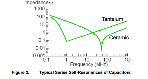
No, you cannot do that here. The various caps have different resonant/corner frequencies. It's okay to add them up when doing say a bulk filter for a power supply (e.g. use two 2200uF in parallel) or the bulk reservoir caps for a board (say several 220uF spread on the board, typically on a diagonal pattern). But you cannot "add up" 100nF + 4.7uF on a supply rail. These two serve different purpose. The larger one (uF) becomes an inductor at high frequency due to parasitics. That's why you need the smaller (nF) one in different tech. Analog's app note MT-101 discusses this in detail. It's about opamps, but applies to the supply rails of most chips. TI has a similar appnote SLOA069; here's an illustrative graph from it (but this is just the general idea regarding the effects of parasitics):

enter image description here

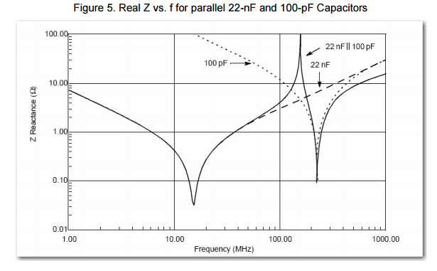
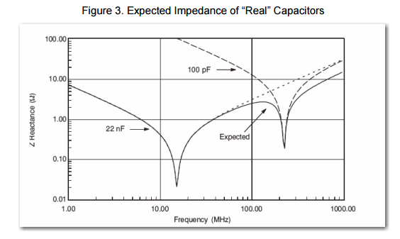
Cypress has a note AN1032 for higher speeds used in data communication. Even if you use the same tech for the caps here's what happens in calculation vs. reality when you parallel them:

enter image description here enter image description here

That's why it's a good idea to go (at least as a start/prototype) with the values recommended in the datasheet for a particular chip. Hopefully the manufactuerer of the IC tested the effect of the combo they recommend on the real chip before putting in the datasheet.

Now, as a matter of practicality, I have combined/added the values of eletrolytics for nearby components, for example I used one 22uF eletrolytic instead of two 10uF ones for nearby opamps (which saves a bit of board space). But I left the ceramics separate for each opamp. I'm not an experienced designer and didn't do sophisticated calculations... and got away with that. I don't know how more sophisticated engineers solve this kind of problem, i.e. combining networks of caps. It's probably hard given all the variables including parasitics.
added 751 characters in body
Source Link

I could simply use 1 equivalent capacitor with Ceq = C1 + C2 + C3?

No, you cannot do that here. The various caps have different resonant/corner frequencies. It's okay to add them up when doing say a bulk filter for a power supply (e.g. use two 2200uF in parallel) or the bulk reservoir caps for a board (say several 220uF spread on the board, typically on a diagonal pattern). But you cannot "add up" 100nF + 4.7uF on a supply rail. These two serve different purpose. The larger one (uF) becomes an inductor at high frequency due to parasitics. That's why you need the smaller (nF) one in different tech. Analog's app note MT-101 discusses this in detail. It's about opamps, but applies to the supply rails of most chips. TI has a similar appnote SLOA069; here's an illustrative graph from it (but this is just the general idea regarding the effects of parasitics):

enter image description here

Cypress has a note AN1032 for higher speeds used in data communication. Even if you use the same tech for the caps here's what happens in calculation vs. reality when you parallel them:

enter image description here enter image description here

That's why it's a good idea to go (at least as a start/prototype) with the values recommended in the datasheet for a particular chip. Hopefully the manufactuerer of the IC tested the effect of the combo they recommend on the real chip before putting in the datasheet.

I could simply use 1 equivalent capacitor with Ceq = C1 + C2 + C3?

No, you cannot do that here. The various caps have different resonant/corner frequencies. It's okay to add them up when doing say a bulk filter for a power supply (e.g. use two 2200uF in parallel) or the bulk reservoir caps for a board (say several 220uF spread on the board, typically on a diagonal pattern). But you cannot "add up" 100nF + 4.7uF on a supply rail. These two serve different purpose. The larger one (uF) becomes an inductor at high frequency due to parasitics. That's why you need the smaller (nF) one in different tech. Analog's app note MT-101 discusses this in detail. It's about opamps, but applies to the supply rails of most chips. TI has a similar appnote SLOA069; here's an illustrative graph from it:

enter image description here

I could simply use 1 equivalent capacitor with Ceq = C1 + C2 + C3?

No, you cannot do that here. The various caps have different resonant/corner frequencies. It's okay to add them up when doing say a bulk filter for a power supply (e.g. use two 2200uF in parallel) or the bulk reservoir caps for a board (say several 220uF spread on the board, typically on a diagonal pattern). But you cannot "add up" 100nF + 4.7uF on a supply rail. These two serve different purpose. The larger one (uF) becomes an inductor at high frequency due to parasitics. That's why you need the smaller (nF) one in different tech. Analog's app note MT-101 discusses this in detail. It's about opamps, but applies to the supply rails of most chips. TI has a similar appnote SLOA069; here's an illustrative graph from it (but this is just the general idea regarding the effects of parasitics):

enter image description here

Cypress has a note AN1032 for higher speeds used in data communication. Even if you use the same tech for the caps here's what happens in calculation vs. reality when you parallel them:

enter image description here enter image description here

That's why it's a good idea to go (at least as a start/prototype) with the values recommended in the datasheet for a particular chip. Hopefully the manufactuerer of the IC tested the effect of the combo they recommend on the real chip before putting in the datasheet.

Source Link

I could simply use 1 equivalent capacitor with Ceq = C1 + C2 + C3?

No, you cannot do that here. The various caps have different resonant/corner frequencies. It's okay to add them up when doing say a bulk filter for a power supply (e.g. use two 2200uF in parallel) or the bulk reservoir caps for a board (say several 220uF spread on the board, typically on a diagonal pattern). But you cannot "add up" 100nF + 4.7uF on a supply rail. These two serve different purpose. The larger one (uF) becomes an inductor at high frequency due to parasitics. That's why you need the smaller (nF) one in different tech. Analog's app note MT-101 discusses this in detail. It's about opamps, but applies to the supply rails of most chips. TI has a similar appnote SLOA069; here's an illustrative graph from it:

enter image description here