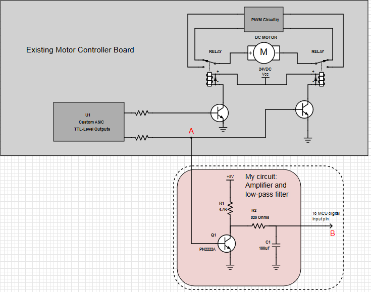
I am working with a motor control board which controls a DC motor. The motor can be reversed (speed and the speed can be controlled by the boarddirection).
This board uses two SPDT relays for reversingdirection, and some sort of PWM to controlfor speed.
I have drawnHere's an abbreviated schematic of how I think this system works, as well asincluding my own circuitrycircuit.
My task isI need to determine which directionfeed the motor is being run. I need to input this informationdirection to a single binary digital pin on a standalone microcontrollerMCU using TTL levels.
I determined that the controller energizes one relay for each direction of rotation. The output of the controller ASIC appears to be 5V TTL logic level. However, after the signal passes throughtapped the resistors, it can be measuredcircuit at point "A" as, which outputs 0V when relay is not energized and 0.8V (energized relay) and 0V (de-energized relay)when energized. This corresponds with the motor directions.
I would prefer to avoid tapping this circuit in front of the resistor, because it's a SMD chip and the relay is very close to the chip, leaving very little room for soldering. So I connected using an existing via at point "A" instead, and decided to amplifyamplified this signal back to TTL levels using the circuitrycircuit shown.
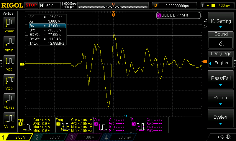
This works fineperfectly, except when the motor begins to apply heavy PWM to the control circuitis running slowly (when running theheavy PWM applied to motor slowlyoutputs). The relay remains energized duringIn this operation, but I can see largestate there are repeated spikes appear at point A, which are amplified to point B, and B (see this example) which cause the microcontroller to detect changes in value. Thus, the Direction value beginsMCU to oscillate whenthink the motor runs slowlypin has changed state.
I observed these spikes with an oscilloscope and decided that I needed aYou can see the low-pass filter to attenuate them.
I looked up the appropriate resistor/capacitor valuesintended to attenuate frequenciesanything above 2Hz, and you can see the results shown on the schematic2 Hz.
However the problem is that this But it doesn't work: thefilter these spikes are still present, and continue to confuse my MCUfor some reason.
Does anyone have any suggestions for cleaning up this signal or blocking these spikes to ensure a clean digital 0V/5V TTL level is passed to the MCU?
Did I implement the high-pass filter incorrectly? Why doesn't it block these spikes?The controller and my circuit share a common ground.
Thank you for any advice!


