formatting
Source Link
Sredni Vashtar
  • 4.1k
  • 2
  • 18
  • 26
  1. The input characteristic makes current the better 'control variable' in most amplifying/switching applications.
  2. In the simplest, piecewise linear model of the BJT, VBE\$V_{BE}\$ is fixed and only current can be changed.
  3. In all more sophisticated models, current and voltage are inseparable so you can see the device both as current-controlled and as voltage-controlled depending on convenience (but point 1 still stands).
enter image description here
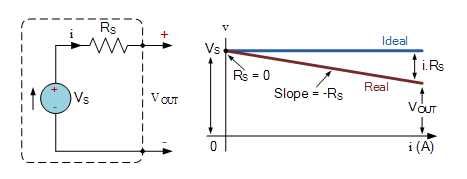
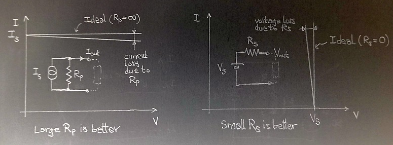
Current and voltage generators characteristics on the VI planeCurrent and voltage generators characteristics on the VI plane

What does this mean, in practice? That a current generator is able to supply a given current almost indipendentlyindependently from the load (but the voltage across it will change accordingly to the value of the load resistance), while a voltage generator is able to supply a given voltage almost indepedentlyindependently from the load (and in this case it's the current that will adapt to the load.)

enter image description here
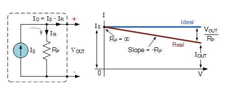
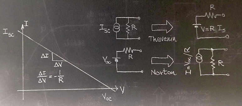
A non-ideal linear generator and its Thevenin and Norton equivalentsA non-ideal linear generator and its Thevenin and Norton equivalents

Generally speaking, a current generator has a very large internal resistance (ideally infinite), while a voltage generator has a very small internal resistance (ideally zero); when the internal resistance value is finite, 'large' and 'small' are concepts relative to the magnitude of the load and the admissible intervals of voltage and current for the particular circuit the generator is part of.

enter image description here
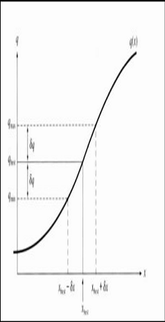
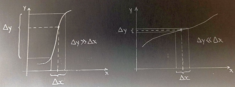
Propagation of uncertainty from the independent variable to the dependent variablePropagation of uncertainty from the independent variable to the dependent variable

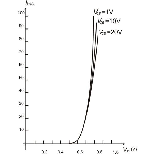
When there is uncertainty in the variables, it is better to chose as controlling variable the variable whose uncertainty will not be 'amplified'. It is basic error propagation theory (a good first textbook on this topicetopics is "An introduction to error analysis""An introduction to error analysis", by Taylor). In the case of the BJT, given the exponential input characteristic (IB vs VBE) that leaves VBE almost constant on the range of admissable currents, it is current you would like to see as the controlling variable. The bottom line is that it's easier to distinguish between 10 and 40 microamperes (1 to 4 ratio) than it is to tell 0.66 and 0.70 V apart (1 to 1.06 ratio).

This is probably the first reason why the BJT is considered a current controlled device. This is the simplest model for the BJT, as shown by Chua, Desoer and Kuh in their "Linear and Nonlinear Circuits""Linear and Nonlinear Circuits":

Someone will jump on their seat screaming "WHAT? You are using \$\beta\$ to design an amplifier to be put into worldwide production for mission-critical nuclear applications? Also, where do you think \$\beta\$ come from? Moreover, don't you know that \$\beta\$ can change by as much as ninetynine gazillions percent just by looking at it in a funny way?"WHAT? You are using \$\beta\$ to design an amplifier to be put into worldwide production for mission-critical nuclear applications? Also, where do you think \$\beta\$ come from? Moreover, don't you know that \$\beta\$ can change by as much as ninetynine gazillions percent just by looking at it in a funny way?"
The point is that for a given transistor you have a reasonably defined value of beta (you can measure it beforehand, so it does not matter if the production lot shows a shameful dispersion) and if you do not wander too far, you can reasonably ignore its variation with the other electrical parameters. Note that the one I just described is a simplified model that does not model variations of beta with temperature, current, or even hair color; it's a simplified model that catches the gist of transistor action, much in the same way as the sometimes reviled "transistor man" from The Art of ElectronicsThe Art of Electronics.

You might want to compare this model with the simplest model for a MosfetMOSFET: page 151 of Chua has that one too.

As you can see, the gate current is fixed (at zero to be pedantic), a condition dual to that shown in the BJT: the I-V input characteristic is horizontal. The only control you have here is by means of vgs. Does this mean we are negating the existence of the tunnel effect? Nope, this is just a model. A simplified model that, among other things, does not consider tunneling but still manages to show why in a mosfetMOSFET you act on the gate-source voltage.

Are these two gentlemen oblivious of the role played by quantum mechanics in the band theory of solids? Have they not heard of quantum statistics? Do they even know what a hole is (not to mention the tempco)? Could they have forgotten that applying voltages could modify the energy level profiles attributed to valence and conduction bands? I don't think so. They simply chose a simpler model to explain how one can intepretinterpret the so called transistor action.
Artist Bruno Munari once said: "To complicate is simple, to simplify is complicated. ... Everybody is able to complicate. Only a few can simplify". Among others, Chua, Desoer, Kuh, Eisberg, and Resnick chose to simplify.

So, at this point we can think that current control in the BJT is a consequence of an excessively simplified model. But
But wait! There is more....

Real transistors have non-discontinuous characteristics, and a BJT exhibit an exponential input characteristic (Vbe, Ib) and a logarithmic output characteristic (Vce, Ic). Let's see how the propagation of uncertainties plays out in a practical (albeit exaggerated) example. Let's focus on the input characteristic (Vbe, Ib) for VCE=10V\$V_{CE}=10V\$ in the following images:

enter image description here
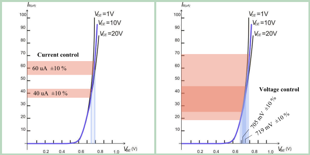
Background image of "real BJT" characteristics taken from here (the set values of current and voltage have been chosen to match the example in the text, but the conjugate variable values are a bit off w.r.t. the actual simulation).Background image of "real BJT" characteristics taken from here (the set values of current and voltage have been chosen to match the example in the text, but the conjugate variable values are a bit off w.r.t. the actual simulation).
The key takeaway here is that current control with a lousy generator makes it possible to distinguish different states, while voltage control will lead right away to a superposition in all values.The key takeaway here is that current control with a lousy generator makes it possible to distinguish different states, while voltage control will lead right away to a superposition in all values.

Let's say you want to use this BJT to produce a collector current of 10 mA on odd days and 15 mA on even days. You
You tasked a German lab with accurately measure the betaaccurately measuring the beta of the particular transistor in your possession and it came out as 250 over the range of interest (at the controlled temperature you intend to run the experiment). Since you've spent all of your money in the beta certification program, let's say you only have access to current and voltage generators with ideal internal resistances but marred by an accuracy of ±10% (yes, this is the part where I exaggerate).

ib = 36-44 uA --> ic = 9-11 mA 
ib = 54-66 uA --> ic = 13.5-16.5 mA

enter image description here
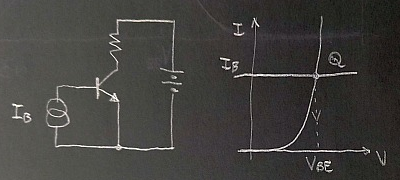
A bjt driven by an ideal current sourceA bjt driven by an ideal current source

enter image description here
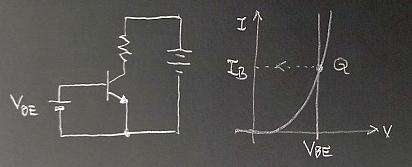
A BJT driven by an ideal voltage sourceA BJT driven by an ideal voltage source

You can either compute the logarithm, or use the full Ebers-Moll model to compute the value, or maybe ask the manufacturer to provide you with a suitable chart. But let's say you've determined it's precisely 0.705 and 0.719V (these values come from a simulation.)
When you set those precise values, your low-cost ±10% accurate generator will supply a voltage with the following uncertaintesuncertainties

0.6345 - 0.7755 V --> back to Ebers-Moll, to compute ic, ... too bad the uncertainty will be exponentiated...

0.6471 - 0.7909 V V --> no, wait, before computing...

enter image description here
A BJT driven by a real source with a slanted characteristic lineA BJT driven by a real source with a slanted characteristic line

enter image description here
Setting Ic = 10mA and Ic = 15mA with a real world generator.Setting Ic = 10mA and Ic = 15mA with a real world generator.
Is the input one-port behaving more like a voltage generator, or more like a current generator?Is the input one-port behaving more like a voltage generator, or more like a current generator?

I am not getting into the design procedure of the 'voltage control guy' (ask them how they arrive to determine the values with real components).
Irregardless

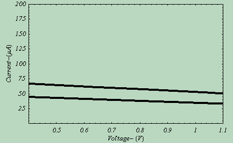
Irregardless on the procedure followed to 'design' the two circuits, let's see what the BE diode of the BJT sees. It's a small battery in series with a reasonably high resistance. I say this behaves more like a current generator than a voltage generator. If we plot the VI characteristic of the one port formed by Vbatt and RB (for RB = 65 kohm and RB = 43.3 kohm) on a range of typical base-emitter voltages (0.5 to 1.2 V) and base currents (0 to 200 uA) we see this:

enter image description here
Within these ranges, it looks like the BJT is driven by a reasonable approximation of a current generatorWithin these ranges, it looks like the BJT is driven by a reasonable approximation of a current generator

enter image description here
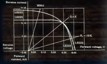
Solar cell characteristics - adapted from Millman, "Electronic Devices and Circuits" (1967)Solar cell characteristics - adapted from Millman, "Electronic Devices and Circuits" (1967)

enter image description here
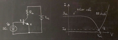
BJT circuit powered by a single cell: bad operating pointBJT circuit powered by a single cell: bad operating point

enter image description here
A double cell circuit results in a better operating pointA double cell circuit results in a better operating point

enter image description here
With three solar cells, the BJT is driven by a constant current generator with current determined by cell illuminationWith three solar cells, the BJT is driven by a constant current generator with current determined by cell illumination

It is therefore easy, when following this path, to think that current control is a white lie told to first year students, while experienced and savysavvy engineers know Ebers-Moll and device physics, and it's clear to them that it's voltage that controls the currents in a BJT. Well, not so fast! For starters, the dependence on Vbe shown in the Ebers-Moll model is not implying a cause-effect relationship. It's just simpler to write the equations in that way. Nobody forbids you from using inverse functions. And this is not an opinion: the expression of the Ebers Moll model in the form V = V(I) can be found no less than in the original 1954 Ebers and Moll paperthe original 1954 Ebers and Moll paper (and Millman's textbooks). And then there are charge control models of the BJT that go beyond voltage or current control.

  1. The input characteristic makes current the better 'control variable' in most amplifying/switching applications.
  2. In the simplest, piecewise linear model of the BJT, VBE is fixed and only current can be changed.
  3. In all more sophisticated models, current and voltage are inseparable so you can see the device both as current-controlled and as voltage-controlled depending on convenience (but point 1 still stands).

enter image description here
Current and voltage generators characteristics on the VI plane

What does this mean, in practice? That a current generator is able to supply a given current almost indipendently from the load (but the voltage across it will change accordingly to the value of the load resistance), while a voltage generator is able to supply a given voltage almost indepedently from the load (and in this case it's the current that will adapt to the load.)

enter image description here
A non-ideal linear generator and its Thevenin and Norton equivalents

Generally speaking, a current generator has a very large internal resistance (ideally infinite), while a voltage generator has a very small internal resistance (ideally zero); when the value is finite, 'large' and 'small' are concepts relative to the magnitude of the load and the admissible intervals of voltage and current for the particular circuit the generator is part of.

enter image description here
Propagation of uncertainty from the independent variable to the dependent variable

When there is uncertainty in the variables, it is better to chose as controlling variable the variable whose uncertainty will not be 'amplified'. It is basic error propagation theory (a good first textbook on this topice is "An introduction to error analysis", by Taylor). In the case of the BJT, given the exponential input characteristic (IB vs VBE) that leaves VBE almost constant on the range of admissable currents, it is current you would like to see as the controlling variable. The bottom line is that it's easier to distinguish between 10 and 40 microamperes (1 to 4 ratio) than it is to tell 0.66 and 0.70 V apart (1 to 1.06 ratio).

This is probably the first reason why the BJT is considered a current controlled device. This is the simplest model for the BJT, as shown by Chua, Desoer and Kuh in their "Linear and Nonlinear Circuits":

Someone will jump on their seat screaming "WHAT? You are using \$\beta\$ to design an amplifier to be put into worldwide production for mission-critical nuclear applications? Also, where do you think \$\beta\$ come from? Moreover, don't you know that \$\beta\$ can change by as much as ninetynine gazillions percent just by looking at it in a funny way?"
The point is that for a given transistor you have a reasonably defined value of beta (you can measure it beforehand, so it does not matter if the production lot shows a shameful dispersion) and if you do not wander too far, you can reasonably ignore its variation with the other electrical parameters. Note that the one I just described is a simplified model that does not model variations of beta with temperature, current, or even hair color; it's a simplified model that catches the gist of transistor action, much in the same way as the sometimes reviled "transistor man" from The Art of Electronics.

You might want to compare this model with the simplest model for a Mosfet: page 151 of Chua has that one too.

As you can see, the gate current is fixed (at zero to be pedantic), a condition dual to that shown in the BJT: the I-V input characteristic is horizontal. The only control you have here is by means of vgs. Does this mean we are negating the existence of the tunnel effect? Nope, this is just a model. A simplified model that, among other things, does not consider tunneling but still manages to show why in a mosfet you act on the gate-source voltage.

Are these two gentlemen oblivious of the role played by quantum mechanics in the band theory of solids? Have they not heard of quantum statistics? Do they even know what a hole is (not to mention the tempco)? Could they have forgotten that applying voltages could modify the energy level profiles attributed to valence and conduction bands? I don't think so. They simply chose a simpler model to explain how one can intepret the so called transistor action.
Artist Bruno Munari once said: "To complicate is simple, to simplify is complicated. ... Everybody is able to complicate. Only a few can simplify". Among others, Chua, Desoer, Kuh, Eisberg, and Resnick chose to simplify.

So, at this point we can think that current control in the BJT is a consequence of an excessively simplified model. But wait! There is more....

Real transistors have non-discontinuous characteristics, and a BJT exhibit an exponential input characteristic (Vbe, Ib) and a logarithmic output characteristic (Vce, Ic). Let's see how the propagation of uncertainties plays out in a practical (albeit exaggerated) example. Let's focus on the input characteristic (Vbe, Ib) for VCE=10V in the following images:

enter image description here
Background image of "real BJT" characteristics taken from here (the set values of current and voltage have been chosen to match the example in the text, but the conjugate variable values are a bit off w.r.t. the actual simulation). The key takeaway here is that current control with a lousy generator makes it possible to distinguish different states, while voltage control will lead right away to a superposition in all values.

Let's say you want to use this BJT to produce a collector current of 10 mA on odd days and 15 mA on even days. You tasked a German lab with accurately measure the beta of the particular transistor in your possession and it came out as 250 over the range of interest (at the controlled temperature you intend to run the experiment). Since you've spent all of your money in the beta certification program, let's say you only have access to current and voltage generators with ideal internal resistances but marred by an accuracy of ±10% (yes, this is the part where I exaggerate).

ib = 36-44 uA --> ic = 9-11 mA ib = 54-66 uA --> ic = 13.5-16.5 mA

enter image description here
A bjt driven by an ideal current source

enter image description here
A BJT driven by an ideal voltage source

You can either compute the logarithm, or use the full Ebers-Moll model to compute the value, or maybe ask the manufacturer to provide you with a suitable chart. But let's say you've determined it's precisely 0.705 and 0.719V (these values come from a simulation.)
When you set those precise values, your low-cost ±10% accurate generator will supply a voltage with the following uncertaintes

0.6345 - 0.7755 V -> back to Ebers-Moll, to compute ic, ... too bad the uncertainty will be exponentiated...

0.6471 - 0.7909 V V -> no, wait, before computing...

enter image description here
A BJT driven by a real source with a slanted characteristic line

enter image description here
Setting Ic = 10mA and Ic = 15mA with a real world generator.
Is the input one-port behaving more like a voltage generator, or more like a current generator?

I am not getting into the design procedure of the 'voltage control guy' (ask them how they arrive to determine the values with real components).
Irregardless on the procedure followed to 'design' the two circuits, let's see what the BE diode of the BJT sees. It's a small battery in series with a reasonably high resistance. I say this behaves more like a current generator than a voltage generator. If we plot the VI characteristic of the one port formed by Vbatt and RB (for RB = 65 kohm and RB = 43.3 kohm) on a range of typical base-emitter voltages (0.5 to 1.2 V) and base currents (0 to 200 uA) we see this:

enter image description here
Within these ranges, it looks like the BJT is driven by a reasonable approximation of a current generator

enter image description here
Solar cell characteristics - adapted from Millman, "Electronic Devices and Circuits" (1967)

enter image description here
BJT circuit powered by a single cell: bad operating point

enter image description here
A double cell circuit results in a better operating point

enter image description here
With three solar cells, the BJT is driven by a constant current generator with current determined by cell illumination

It is therefore easy, when following this path, to think that current control is a white lie told to first year students, while experienced and savy engineers know Ebers-Moll and device physics, and it's clear to them that it's voltage that controls the currents in a BJT. Well, not so fast! For starters, the dependence on Vbe shown in the Ebers-Moll model is not implying a cause-effect relationship. It's just simpler to write the equations in that way. Nobody forbids you from using inverse functions. And this is not an opinion: the expression of the Ebers Moll model in the form V = V(I) can be found no less than in the original 1954 Ebers and Moll paper (and Millman's textbooks). And then there are charge control models of the BJT that go beyond voltage or current control.

  1. The input characteristic makes current the better 'control variable' in most amplifying/switching applications.
  2. In the simplest, piecewise linear model of the BJT, \$V_{BE}\$ is fixed and only current can be changed.
  3. In all more sophisticated models, current and voltage are inseparable so you can see the device both as current-controlled and as voltage-controlled depending on convenience (but point 1 still stands).

enter image description here
Current and voltage generators characteristics on the VI plane

What does this mean, in practice? That a current generator is able to supply a given current almost independently from the load (but the voltage across it will change accordingly to the value of the load resistance), while a voltage generator is able to supply a given voltage almost independently from the load (and in this case it's the current that will adapt to the load.)

enter image description here
A non-ideal linear generator and its Thevenin and Norton equivalents

Generally speaking, a current generator has a very large internal resistance (ideally infinite), while a voltage generator has a very small internal resistance (ideally zero); when the internal resistance value is finite, 'large' and 'small' are concepts relative to the magnitude of the load and the admissible intervals of voltage and current for the particular circuit the generator is part of.

enter image description here
Propagation of uncertainty from the independent variable to the dependent variable

When there is uncertainty in the variables, it is better to chose as controlling variable the variable whose uncertainty will not be 'amplified'. It is basic error propagation theory (a good first textbook on this topics is "An introduction to error analysis", by Taylor). In the case of the BJT, given the exponential input characteristic (IB vs VBE) that leaves VBE almost constant on the range of admissable currents, it is current you would like to see as the controlling variable. The bottom line is that it's easier to distinguish between 10 and 40 microamperes (1 to 4 ratio) than it is to tell 0.66 and 0.70 V apart (1 to 1.06 ratio).

This is probably the first reason why the BJT is considered a current controlled device. This is the simplest model for the BJT, as shown by Chua, Desoer and Kuh in their "Linear and Nonlinear Circuits":

Someone will jump on their seat screaming "WHAT? You are using \$\beta\$ to design an amplifier to be put into worldwide production for mission-critical nuclear applications? Also, where do you think \$\beta\$ come from? Moreover, don't you know that \$\beta\$ can change by as much as ninetynine gazillions percent just by looking at it in a funny way?"
The point is that for a given transistor you have a reasonably defined value of beta (you can measure it beforehand, so it does not matter if the production lot shows a shameful dispersion) and if you do not wander too far, you can reasonably ignore its variation with the other electrical parameters. Note that the one I just described is a simplified model that does not model variations of beta with temperature, current, or even hair color; it's a simplified model that catches the gist of transistor action, much in the same way as the sometimes reviled "transistor man" from The Art of Electronics.

You might want to compare this model with the simplest model for a MOSFET: page 151 of Chua has that one too.

As you can see, the gate current is fixed (at zero to be pedantic), a condition dual to that shown in the BJT: the I-V input characteristic is horizontal. The only control you have here is by means of vgs. Does this mean we are negating the existence of the tunnel effect? Nope, this is just a model. A simplified model that, among other things, does not consider tunneling but still manages to show why in a MOSFET you act on the gate-source voltage.

Are these two gentlemen oblivious of the role played by quantum mechanics in the band theory of solids? Have they not heard of quantum statistics? Do they even know what a hole is (not to mention the tempco)? Could they have forgotten that applying voltages could modify the energy level profiles attributed to valence and conduction bands? I don't think so. They simply chose a simpler model to explain how one can interpret the so called transistor action.
Artist Bruno Munari once said: "To complicate is simple, to simplify is complicated. ... Everybody is able to complicate. Only a few can simplify". Among others, Chua, Desoer, Kuh, Eisberg, and Resnick chose to simplify.

So, at this point we can think that current control in the BJT is a consequence of an excessively simplified model.
But wait! There is more....

Real transistors have non-discontinuous characteristics, and a BJT exhibit an exponential input characteristic (Vbe, Ib) and a logarithmic output characteristic (Vce, Ic). Let's see how the propagation of uncertainties plays out in a practical (albeit exaggerated) example. Let's focus on the input characteristic (Vbe, Ib) for \$V_{CE}=10V\$ in the following images:

enter image description here
Background image of "real BJT" characteristics taken from here (the set values of current and voltage have been chosen to match the example in the text, but the conjugate variable values are a bit off w.r.t. the actual simulation).
The key takeaway here is that current control with a lousy generator makes it possible to distinguish different states, while voltage control will lead right away to a superposition in all values.

Let's say you want to use this BJT to produce a collector current of 10 mA on odd days and 15 mA on even days.
You tasked a German lab with accurately measuring the beta of the particular transistor in your possession and it came out as 250 over the range of interest (at the controlled temperature you intend to run the experiment). Since you've spent all of your money in the beta certification program, let's say you only have access to current and voltage generators with ideal internal resistances but marred by an accuracy of ±10% (yes, this is the part where I exaggerate).

ib = 36-44 uA --> ic = 9-11 mA 
ib = 54-66 uA --> ic = 13.5-16.5 mA

enter image description here
A bjt driven by an ideal current source

enter image description here
A BJT driven by an ideal voltage source

You can either compute the logarithm, or use the full Ebers-Moll model to compute the value, or maybe ask the manufacturer to provide you with a suitable chart. But let's say you've determined it's precisely 0.705 and 0.719V (these values come from a simulation.)
When you set those precise values, your low-cost ±10% accurate generator will supply a voltage with the following uncertainties

0.6345 - 0.7755 V --> back to Ebers-Moll, to compute ic, ... too bad the uncertainty will be exponentiated...

0.6471 - 0.7909 V V --> no, wait, before computing...

enter image description here
A BJT driven by a real source with a slanted characteristic line

enter image description here
Setting Ic = 10mA and Ic = 15mA with a real world generator.
Is the input one-port behaving more like a voltage generator, or more like a current generator?

I am not getting into the design procedure of the 'voltage control guy' (ask them how they arrive to determine the values with real components).

Irregardless on the procedure followed to 'design' the two circuits, let's see what the BE diode of the BJT sees. It's a small battery in series with a reasonably high resistance. I say this behaves more like a current generator than a voltage generator. If we plot the VI characteristic of the one port formed by Vbatt and RB (for RB = 65 kohm and RB = 43.3 kohm) on a range of typical base-emitter voltages (0.5 to 1.2 V) and base currents (0 to 200 uA) we see this:

enter image description here
Within these ranges, it looks like the BJT is driven by a reasonable approximation of a current generator

enter image description here
Solar cell characteristics - adapted from Millman, "Electronic Devices and Circuits" (1967)

enter image description here
BJT circuit powered by a single cell: bad operating point

enter image description here
A double cell circuit results in a better operating point

enter image description here
With three solar cells, the BJT is driven by a constant current generator with current determined by cell illumination

It is therefore easy, when following this path, to think that current control is a white lie told to first year students, while experienced and savvy engineers know Ebers-Moll and device physics, and it's clear to them that it's voltage that controls the currents in a BJT. Well, not so fast! For starters, the dependence on Vbe shown in the Ebers-Moll model is not implying a cause-effect relationship. It's just simpler to write the equations in that way. Nobody forbids you from using inverse functions. And this is not an opinion: the expression of the Ebers Moll model in the form V = V(I) can be found no less than in the original 1954 Ebers and Moll paper (and Millman's textbooks). And then there are charge control models of the BJT that go beyond voltage or current control.

added 14 characters in body
Source Link
Sredni Vashtar
  • 4.1k
  • 2
  • 18
  • 26

The thing to notice here is that when ib changes greatly, by 100s of percents, vbe changes by relatively small amounts, just a handful of percents. This is because of the exponential relation ib = I(vbe), or equivalently the logarithmic relation vbe = V(ib), of the B-E junction.
Let's

Let's say you want to use this BJT to produce a collector current of 10 mA on odd days and 15 mA on even days. You tasked a German lab with accurately measure the beta of the particular transistor in your possession and it came out as 250 over the range of interest (at the controlled temperature you intend to run the experiment). Since you've spent all of your money in the beta certification program, let's say you only have access to current and voltage generators with ideal internal resistances but marred by an accuracy of ±10% (yes, this is the part where I exaggerate).

to find the value of ib that you have to set. A simple division will show that the nominal values of 10 and 15 mA of ic require nominal values of 40 eand 60 uA for ib. Given the accuracy of your current generator, you will expect to see the following current ranges in input and output:

You can either compute the logarithm, or use the full Ebers-Moll model to compute the value, or maybe ask the manufacturer to provide you with a suitable chart. But let's say you've determined it's precisely 0.705 and 0.719V (these values come from a simulation.) 
When you set those precise values, your low-cost ±10% accurate generator will supply a voltage with the following uncertaintes

The figure at the beginning of this subsection summarizes how current control is the preferred way to drive your transistor. With current control, even if we allow a ±10% error on the measured value of beta, we can still (barely, but still) make out the two ranges of current (9 - 11 mA vs 13.5 - 16.5 mA) corresponding to odd and even days. 
With voltage control, if we add a ±10% error on the computed (or graphically deduced) value of voltage, you are already lost in VBE uncertainty. And if that wasn't enough, that uncertainty will also be amplified to an even worse uncertainty in the values of IB and IC.

It's clear that this cell alone won't be operating in the constant current region, but it will instead appear as a weak voltage generator, incapable of driving the transistor as we wish.
But if we put two such cells in series, their combined characteristic will have the same short circuit current and double the open circuit voltage. Now the intersection of generator (solar cell) and load (the BE diode) will be in a better position, near the region where the current appear to be constant. If we use three cells in series, we achieve a reasonably stiff constant current generator: it will deliver 50 uA for a wide range of loads, including the load represented by the BJT base-emitter junction.   

enter image description here
A double cell circuit results in a better operating point

The thing to notice here is that when ib changes greatly, by 100s of percents, vbe changes by relatively small amounts, just a handful of percents. This is because of the exponential relation ib = I(vbe), or equivalently the logarithmic relation vbe = V(ib), of the B-E junction.
Let's say you want to use this BJT to produce a collector current of 10 mA on odd days and 15 mA on even days. You tasked a German lab with accurately measure the beta of the particular transistor in your possession and it came out as 250 over the range of interest (at the controlled temperature you intend to run the experiment). Since you've spent all of your money in the beta certification program, let's say you only have access to current and voltage generators with ideal internal resistances but marred by an accuracy of ±10% (yes, this is the part where I exaggerate).

to find the value of ib that you have to set. A simple division will show that the nominal values of 10 and 15 mA of ic require nominal values of 40 e 60 uA for ib. Given the accuracy of your current generator, you will expect to see the following current ranges in input and output:

You can either compute the logarithm, or use the full Ebers-Moll model to compute the value, or maybe ask the manufacturer to provide you with a suitable chart. But let's say you've determined it's precisely 0.705 and 0.719V (these values come from a simulation.) When you set those precise values, your low-cost ±10% accurate generator will supply a voltage with the following uncertaintes

The figure at the beginning of this subsection summarizes how current control is the preferred way to drive your transistor. With current control, even if we allow a ±10% error on the measured value of beta, we can still (barely, but still) make out the two ranges of current (9 - 11 mA vs 13.5 - 16.5 mA) corresponding to odd and even days. With voltage control, if we add a ±10% error on the computed (or graphically deduced) value of voltage, you are already lost in VBE uncertainty. And if that wasn't enough, that uncertainty will also be amplified to an even worse uncertainty in the values of IB and IC.

It's clear that this cell alone won't be operating in the constant current region, but it will instead appear as a weak voltage generator, incapable of driving the transistor as we wish.
But if we put two such cells in series, their combined characteristic will have the same short circuit current and double the open circuit voltage. Now the intersection of generator (solar cell) and load (the BE diode) will be in a better position, near the region where the current appear to be constant. If we use three cells in series, we achieve a reasonably stiff constant current generator: it will deliver 50 uA for a wide range of loads, including the load represented by the BJT base-emitter junction.  enter image description here
A double cell circuit results in a better operating point

The thing to notice here is that when ib changes greatly, by 100s of percents, vbe changes by relatively small amounts, just a handful of percents. This is because of the exponential relation ib = I(vbe), or equivalently the logarithmic relation vbe = V(ib), of the B-E junction.

Let's say you want to use this BJT to produce a collector current of 10 mA on odd days and 15 mA on even days. You tasked a German lab with accurately measure the beta of the particular transistor in your possession and it came out as 250 over the range of interest (at the controlled temperature you intend to run the experiment). Since you've spent all of your money in the beta certification program, let's say you only have access to current and voltage generators with ideal internal resistances but marred by an accuracy of ±10% (yes, this is the part where I exaggerate).

to find the value of ib that you have to set. A simple division will show that the nominal values of 10 and 15 mA of ic require nominal values of 40 and 60 uA for ib. Given the accuracy of your current generator, you will expect to see the following current ranges in input and output:

You can either compute the logarithm, or use the full Ebers-Moll model to compute the value, or maybe ask the manufacturer to provide you with a suitable chart. But let's say you've determined it's precisely 0.705 and 0.719V (these values come from a simulation.) 
When you set those precise values, your low-cost ±10% accurate generator will supply a voltage with the following uncertaintes

The figure at the beginning of this subsection summarizes how current control is the preferred way to drive your transistor. With current control, even if we allow a ±10% error on the measured value of beta, we can still (barely, but still) make out the two ranges of current (9 - 11 mA vs 13.5 - 16.5 mA) corresponding to odd and even days. 
With voltage control, if we add a ±10% error on the computed (or graphically deduced) value of voltage, you are already lost in VBE uncertainty. And if that wasn't enough, that uncertainty will also be amplified to an even worse uncertainty in the values of IB and IC.

It's clear that this cell alone won't be operating in the constant current region, but it will instead appear as a weak voltage generator, incapable of driving the transistor as we wish.
But if we put two such cells in series, their combined characteristic will have the same short circuit current and double the open circuit voltage. Now the intersection of generator (solar cell) and load (the BE diode) will be in a better position, near the region where the current appear to be constant. If we use three cells in series, we achieve a reasonably stiff constant current generator: it will deliver 50 uA for a wide range of loads, including the load represented by the BJT base-emitter junction. 

enter image description here
A double cell circuit results in a better operating point

Reorganized text, added actual simulated results, solar cell example, links to other answers
Source Link
Sredni Vashtar
  • 4.1k
  • 2
  • 18
  • 26

Preamble I reorganized and expanded this answer to give three reasons why the BJT can be considered "current-controlled":

Let's start with a little digression: what makes a generator a current generator instead of a voltage generator? Look at the V-I characteristics: the one with mostly constant voltage (almost horizontal in the I-V plane) will be called a voltage generator, the one with mostly constant current (almost horizontal in the V-I plane) will be called current generator.

  1. The input characteristic makes current the better 'control variable' in most amplifying/switching applications.
  2. In the simplest, piecewise linear model of the BJT, VBE is fixed and only current can be changed.
  3. In all more sophisticated models, current and voltage are inseparable so you can see the device both as current-controlled and as voltage-controlled depending on convenience (but point 1 still stands).

model of a voltage generator But first, a (double) preamble.

Preamble
model of a current generatorAre we supplying current or voltage?
Let's start with a little digression in basic circuit theory: what makes a generator a current generator instead of a voltage generator? Look at the V-I characteristics: the one with mostly constant current (almost horizontal in the V-I plane) will be called current generator; the one with mostly constant voltage (almost horizontal in the I-V plane, and almost vertical in the V-I plane) will be called a voltage generator.

(Pictures taken from the Electronics Tutorials website)enter image description here
Current and voltage generators characteristics on the VI plane

This is because the 'accent'What does this mean, in practice? That a current generator is onable to supply a given current almost indipendently from the constant quantityload (thebut the voltage or current supplied - whileacross it will change accordingly to the other quantityvalue of the load resistance), while a voltage generator is variable depending onable to supply a given voltage almost indepedently from the load and(and in this case it's the compliance ofcurrent that will adapt to the generator)load. (Note 1)

In a controlled device,The presence of an internal resistance kind of blurs the accent isline between current and voltage generators, since depending on the variable quantity. Givenscale of the exponential inputhorizontal and vertical axes we can show the characteristic, that leaves Vbe almost constant, it is current you would like to see as the controlling variablealmost vertical or almost horizontal. This is a direct consequence of the propagation of errors: when you have a steep function, In reality a small error in the almost constant quantity x will turn intolinear generator with a much bigger error in the widely varying quantity qnon-zero internal resistance can be considered either type (and vice versaconverted to the conjugate type by means of Thevenin's and Norton's transformations).:
error propagation with a steep functionenter image description here
A non-ideal linear generator and its Thevenin and Norton equivalents

Picture taken from "An introduction to error analysis", Taylor and distorted to fit the purpose Generally speaking, a current generator has a very large internal resistance (ideally infinite), while a voltage generator has a very small internal resistance (ideally zero); when the value is finite, 'large' and 'small' are concepts relative to the magnitude of the load and the admissible intervals of voltage and current for the particular circuit the generator is part of.

The bottom lineThe best 'controlling' variable
In generators, the 'accent' is that it's easier to distinguish between 10 e 40 uAon the mostly constant quantity (1 to 4 ratiothe voltage or current supplied) than it, while the other quantity is to separate 0.65variable depending on the load and 0.67 V (1 to 1the compliance of the generator.03 ratio) In a controlled device, on the other hand, the accent is on the variable quantity. 
(Note forYou can see this as a direct consequence of the less flexible mindspropagation of errors: like the more extreme values I used before this editwhen you have a steep function, these are made up values intended to show the contrast between a discernible changesmall error in what you want to see as the controlling variable - the current entering the base - and the feeble changealmost constant quantity x will turn into a much bigger error in the voltage between base and emitterwidely varying quantity q (and vice versa).

The simplest thingenter image description here
Propagation of uncertainty from the independent variable to the dependent variable

You can see why thatWhen there is called current control by pushinguncertainty in the variables, it is better to chose as controlling variable the limitsvariable whose uncertainty will not be 'amplified'. It is basic error propagation theory (a good first textbook on this topice is "An introduction to error analysis", by adoptingTaylor). In the simplest model for acase of the BJT, as shown by Chua, Desoer and Kuh in their "Linear and Nonlinear Circuits": ingiven the following pictures all diodes are idealexponential input characteristic (threshold voltage is zeroIB vs VBE) that leaves VBE almost constant on the range of admissable currents, it is current you would like to see as the controlling variable. The bottom line is that it's easier to distinguish between 10 and so40 microamperes (1 to 4 ratio) than it is series resistance; these are perfectly open circuits when reverse biasedto tell 0.66 and perfect shorts when forward biased0.70 V apart (1 to 1.06 ratio).

Before analyzing examples that show why it's better to resort to base current as a means to control the collector current, let's see how the simplest circuital model of the BJT exclusively allows current control.


Simplified Device Model for the BJT

This is probably the first reason why the BJT is considered a current controlled device. This is the simplest model for the BJT, as shown by Chua, Desoer and Kuh in their "Linear and Nonlinear Circuits":

in the above picture all diodes are ideal (threshold voltage is zero, and so is series resistance; these are perfectly open circuits when reverse biased and perfect shorts when forward biased). E0 adds a threshold voltage to the input characteristic, while transistor action is expressed by ic = beta * ib (in the textbook's notation). Note that current-controlled current generator. Here are the corresponding input and output characteristics

Pretty simple, right? You can compare them with actual characteristics and see that they resemble them, though. Simple as it is, this is a legit model and can be used to model circuits like a common emitter one shown later where, by changing ib (you can't change Vbe in this model, since it's fixed) you changemodify the value of Ic. You can see how you can make ib change by intersecting the input characteristic with the input generator's load line By changing the voltage E1 (not part of the BJT) you change ib (part of the BJT) while vbe is constant at exactly E0. Then you can find the value of ic corresponding to that value of ib, select the corresponding output characteristic and find the voltage by intersection with the output load line.
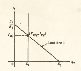
load line in the input circuit

By changing E1 (not part of the BJT) you change ib (part of the BJT). Then you can find the value of ic corresponding to that value of ib, select the corresponding output characteristic and finding the voltage by intersection with the output load line.
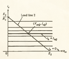
  load line in the output circuit

Someone will jump on their seat screaming "WHAT? You are using beta to design an amplifier to be put into worldwide production for mission-critical nuclear applications? Also, where do you think beta come from? Moreover, don't you know that beta can change by as much as ninetynine gazillions percent just by looking at it?"WHAT? You are using \$\beta\$ to design an amplifier to be put into worldwide production for mission-critical nuclear applications? Also, where do you think \$\beta\$ come from? Moreover, don't you know that \$\beta\$ can change by as much as ninetynine gazillions percent just by looking at it in a funny way?"

The
The point is that for a given transistor you have a reasonably defined value of beta (you can measure it beforehand, so it does not matter if the production lot shows a shameful dispersion) and if you do not wander too far, you can reasonably ignore its variation with the other electrical parameters. Note that thisthe one I just described is a simplified model that does not model variations of beta with temperature, current, or even hair color; it's a simplified model that catches the gist of transistor action, much in the same way as the sometimes reviled "transistor man" from The Art of Electronics.

Can you find the cutoff frequency of the transistor from this model? Nope. Can you explain the Early effect with this model? Nope. Can you account for the differential resistance of the B-E junction with this model? Nope. Can you account for charge pair production due to radiation? Nope. Can you account for second field quantization and the bending of spacetime? Nope.

DoesCan you find the cutoff frequency of the transistor from this model? Nope. Can you explain the Early effect with this model? Nope. Can you account for the differential resistance of the B-E junction with this model? Nope. Can it account for charge pair production due to radiation? Nope. Can you account for second field quantization and the bending of spacetime? Nope.
Does this mean that this model is completely useless? Nope. 
The extremely simplified behavior of this model shows why many textbooks state that BJTs are current controlled. The actual input characteristic resemble that vertical line where you can only vary ib, and not vbe, whose value is considered fixed. (And this is why I made that digression at the beginning of this answer).

You might want to compare this model with the simplest model for a Mosfet: page 151 of Chua has that one too.

As you can see, the gate current is fixed (at zero to be pedantic), a condition dual to that shown in the BJT: the VI-IV input characteristic is horizontal. The only control you have here is by means of vgs. Does this mean we are negating the existence of the tunnel effect? Nope, this is just a model. A simplified model that, among other things, does not consider tunneling but still manages to show why in a MOSFETmosfet you act on the gate-source voltage.

SoThe other current control: \$I_C = \alpha I_E\$
So far we've seen how the (simplified) relationship between ib and ic can be seen as control of ic by means of ib, through beta. But we can also use alpha, why not? Let me quote, verbatim, another textbook that consider BJTs current controlled devices: "Quantum Physics of Atom, Molecules, Solids, Nuclei and Particles 2e", by Eisberg and Resnick, p. 474 (on page 475 is shownreferring to a common base configuration shown on page 475):

Are these two gentlemen oblivious of the role played by quantum mechanics in the band theory of solids? Have they not heard of quantum statistics? Do they even know what a hole is (not to mention the tempco)? Could they have forgotten that applying voltages could modify the energy level profiles attributed to valence and conduction bands? I don't think so. They simply chose a simpler model to explain how one can interpret the so called transistor action.

ArtistAre these two gentlemen oblivious of the role played by quantum mechanics in the band theory of solids? Have they not heard of quantum statistics? Do they even know what a hole is (not to mention the tempco)? Could they have forgotten that applying voltages could modify the energy level profiles attributed to valence and conduction bands? I don't think so. They simply chose a simpler model to explain how one can intepret the so called transistor action.
Artist Bruno Munari once said: "To complicate is simple, to simplify is complicated. ... Everybody is able to complicate. Only a few can simplify". Among others, Chua, Desoer, Kuh, Eisberg, and Resnick chose to simplify.

Who plays in base, first? So, at this point we can think that current control in the BJT is a consequence of an excessively simplified model. But wait! There is more....


Real devices with ideal generators: pure current and pure voltage control

NowReal transistors have non-discontinuous characteristics, back toand a BJT exhibit an exponential input characteristic (almostVbe, Ib) real transistorsand a logarithmic output characteristic (Vce, Ic). This isLet's see how the first vbe chars that I came up with afterpropagation of uncertainties plays out in a practical Google image search(albeit exaggerated) example. Let's focus on the input characteristic (Vbe, Ib) for VCE=10V in the following images:
vbe-ib characteristicsenter image description here
Background image of "real BJT" characteristics taken from here (the set values of current and voltage have been chosen to match the example in the text, but the conjugate variable values are a bit off w.r.t. the actual simulation). The key takeaway here is that current control with a lousy generator makes it possible to distinguish different states, while voltage control will lead right away to a superposition in all values.

Dunno if it's real, but it looks plausible. The thing to notice here is that when ib changes greatly, by 100s of percents, vbe changes by relatively small amounts, just a handful of percents. This is because of the exponential relation ib = I(vbe), or equivalently the logarithmic relation vbe = V(ib), of the B-E junction. 
Let's say you want to use this BJT to produce a collector current of 10 mA on odd days and 15 mA on even days. You havetasked a German lab with accurately measure the beta of the particular transistor in your handpossession and it came out as 250 over the range of interest (at the controlled temperature you intend to run the experiment). Let'sSince you've spent all of your money in the beta certification program, let's say you only have aaccess to current and voltage generatorgenerators with ideal internal resistances but marred by an accuracy of 10%±10% (yes, this is the part where I exaggerate).

Current control : YouIf you use pure current control:
You can use ic = beta ib

$$ I_C = \beta \, I_B $$

to find the value of ib that you have to set. TheA simple division will show that the nominal values of 10 and 15 mA of ic require nominal values of 40 e 60 uA for ib. Given the accuracy of your current generator, you will expect to see the following current ranges in input and output:

Voltage control: You don't believe in betaenter image description here
A bjt driven by an ideal current source

If you use pure voltage control:
You can't use \$I_B = I_C/\beta\$, so you must specify a voltage that create a vbeVBE of... Yes, of what? Go read it on the above graph (but then you'll have to accept the dreadful ic = beta ib relation). I guess you'll have to use the Ebers-Moll model to compute the values to the desired values for ic. But let's say we determined it's precisely 0.65 and 0.67V (just like I have used a precise value for beta, above)

$$V_{BE} = V_{Th} log(\frac{I_C}{I_S})$$
enter image description here
When we try to set those precise values, our china-made 10% accurate generator will supply the followingA BJT driven by an ideal voltage rangessource

You can either compute the logarithm, or use the full Ebers-Moll model to compute the value, or maybe ask the manufacturer to provide you with a suitable chart. But let's say you've determined it's precisely 0.705 and 0.719V (these values come from a simulation.) When you set those precise values, your low-cost ±10% accurate generator will supply a voltage with the following uncertaintes

0.5856345 - 0.7157755 V -> back to Ebers-Moll, to compute ic, ... too bad the uncertainty will be exponentiated...

0.6036471 - 0.7377909 V V -> no, wait, before computing...

I guess it's better to resortThe figure at the beginning of this subsection summarizes how current control is the preferred way to drive your transistor. With current base ascontrol, even if we allow a means±10% error on the measured value of beta, we can still (barely, but still) make out the two ranges of current (9 - 11 mA vs 13.5 - 16.5 mA) corresponding to odd and even days. With voltage control, if we add a ±10% error on the collector currentcomputed (or graphically deduced) value of voltage, you are already lost in VBE uncertainty. And if that wasn't enough, that uncertainty will also be amplified to an even worse uncertainty in the values of IB and IC.

WithAt this point we might have reached the conclusion that current control, even if I allow a 10% error on in the measured value of beta, I can still (barely, but still) make outBJT is the two rangesbest way to deal with the propagation of current (8uncertainty with the steep exponential characteristic.10-12
But wait! There is more.10 mA vs 12.15-18.15 mA) corresponding to odd and even days.


Real devices with real generators: slanted or bent VI chars

With voltage controlIn the real world, ifyour generator will have a non-ideal internal resistance. This means that a voltage generator will show a nonzero series resistance (voltage will be dropped across it as soon as you adddraw a 10% error on the computedcurrent), while a current generator will show a non-infinite parallel resistance (or read from the diagramcurrent will flow in it, as soon as a voltage is dropped across your load.) value
In general real generators behave as good current or voltage generators only within the limits of their compliance. For example, a battery with very low internal resistance behaves as a good voltage generator for wide intervals of currents (and I am being generous since that error is going to be amplifieduntil Rs * Iout becomes appreciable wrt Vs), you are already lost; a battery with a very high series resistance will behave as a reasonable good current generator because Rs will dominate Rs+Rload in uncertaintythe determination of the supplied current (i. This is basic error propagation theorye. the current will be almost independent on the value of the load resistance); a solar cell operating near its short circuit point behaves as an excellent current generator.
Let's drive a BJT of known beta with one of these real generators:

IntermissionExample 1: battery + resistor
In our first example we will use a 3.3V voltage (!) generator and a base resistor (actually two base resistors to be determined: one for odd days, the other for even days). A 'voltage control guy' would use this components to set the controlling voltage between emitter and base, while a 'current control guy' would use it to set the controlling current into base. Our goal is to find the two values of RB that will result in IC = 10 mA, and IC = 15 mA for a BJT of known (measured, certified) beta of 250.

enter image description here
A BJT driven by a real source with a slanted characteristic line

Current control guy's job is easy: the controlling variable is ib, so given the values of 40 and 80 uA (with the above errors) one can compute

$$R_B = \frac{V_{Batt} - V_{BE}}{I_C / \beta}$$

This post is taking time, I'll come back anothereven by assuming VBE constant and equal to add something more0. Let me just address the question7V (uncertainties are on my side). With a know beta of 250, the religion war you might have witnessedresults are RB1 = 65 kohm, and RB2 = 43. What is that all about?3 kohm. Here are the simulations IC = 10.26 mA in the first case, and IC = 15.37 mA for the second one. I'd consider this a success in current control.

Transistor are solid state devices whose inner working needs to be explained using the laws of quantum physics. Given the band structure of the energy levels of electric carriers in solids, it is natural to resort to energy levels to depict the inner workings of these devices. Energyenter image description here
Setting Ic = 10mA and potential are closely relatedIc = 15mA with each other, so most models tend to express relevant quantities in function of potential (difference)sa real world generator. 
The reason I wroteIs the input one-port behaving more like a voltage generator, or more like a current generator?

Note: The dependence on Vbe shown in the Ebers-Moll model is not implying a cause-effect relationship. It's just simpler to write the equations in that way. Nobody forbids you from using inverse functions.

I am not getting into the design procedure of the 'voltage control guy' (ask them how they arrive to determine the values with real components).
Irregardless on the procedure followed to 'design' the two circuits, let's see what the BE diode of the BJT sees. It's a small battery in series with a reasonably high resistance. I say this behaves more like a current generator than a voltage generator. If we plot the VI characteristic of the one port formed by Vbatt and RB (for RB = 65 kohm and RB = 43.3 kohm) on a range of typical base-emitter voltages (0.5 to 1.2 V) and base currents (0 to 200 uA) we see this:

is that voltage and current are closely related too: they are coupled quantities of the effort-flow sortenter image description here
Within these ranges, so that basically you can't have one withoutit looks like the other. ItBJT is a delicate matter though, and I guess one should also consider what it means to create a voltage difference. Is it not createddriven by displacing charges (by electrochemical reaction in a battery, by electromagnetic interaction inreasonable approximation of a mechanicalcurrent generator). I suspect that in the end all devices are basically charge controlled: you move charges from here to there and get a certain effect.

I suspectIf we superpose the 'voltage control' crusadersload line represented by the exponential characteristic of the diode, we obtain a figure that is essentially the same as the one drawn for pure current control. Makes sense, since the large series resistance RB serves the purpose of turning the ideal voltage generator (battery) into something that resembles a current generator.

Example 2: solar cell
Can we get a better approximation of an ideal current generator? Well, yes: solar cells are assumingexcellent approximation of a current generator, as long as they operate in the 'current control' counterpartcorrect part of their VI characteristics. These devices have learned electronicsa nonlinear output characteristic that result in a kind of hybrid behaviour. For example, Have a look at the V-I characteristic of the ancient LS222 model below:
enter image description here
Solar cell characteristics - adapted from Millman, "Electronic Devices and Circuits" (1967)

Where it crosses the I axes it is essentially a horizontal constant current line, therefore it behaves very much like an ideal current generator. On the other hand, for high resistance loads, that is near the V axis on Forrest Mims' booksthe bottom right, it looks more like a voltage generator with a high series resistance (a few hundred ohms.)

Let's try to replicate the 40 to 60 uA ideal constant current generator used to set I_C to 10 and 15 mA in the previous examples. We will have never seento keep the cell in minimal lighting condituon, and we will focus for brevity on a quantum physics50 uA value. Suppose we have only one cell, solid state or semiconductor devices bookwith Voc = 0. They seem45 V and Isc = 50 uA. What is the operating point when we place it across the BE terminals of a BJT? We can try to ignoredetermine it graphically: we draw the meaninggenerator characteristic on the same VI plane with the BE diode characteristic.
enter image description here
BJT circuit powered by a single cell: bad operating point

It's clear that this cell alone won't be operating in the constant current region, but it will instead appear as a weak voltage generator, incapable of controlling variabledriving the transistor as we wish.
But if we put two such cells in series, their combined characteristic will have the variable one chooses to set to actuate a controlsame short circuit current and double the open circuit voltage. I hopeNow the quote from Eisberg & Resnickintersection of generator (two 'solid' physicists if you allow me the punsolar cell) and load (the BE diode) will show thembe in a better position, near the region where the current appear to be constant. If we use three cells in series, we achieve a reasonably stiff constant current generator: it will deliver 50 uA for a wide range of loads, including the load represented by the BJT base-emitter junction. enter image description here
A double cell circuit results in a better operating point

Now, this is not only a current generator from the casepoint of view of the characteristic line in the VI plane, but it is also a current generator in that we set the current by setting the illumination of the cell. N photons per second striking the active area of the cell will result in a current of k N electrons per second flowing in the copper terminals cross section. The value of the voltage across the series, on the other hand, depends on the load. And when we have 50 uA supplied by a series of 3 cells, we get -essentially - the same current we would get simulating an ideal generator.
Change the illumination and with the number of photons per second, the number of electrons per second will vary as well, causing a different value of collector current. It's going to be hard to assert that the voltage across the BE junction is causing the correct number of photons per second per unit area to fly into the solar cell.

enter image description here
With three solar cells, the BJT is driven by a constant current generator with current determined by cell illumination

I call this a practical example of almost ideal current control.
But wait! There is more...

In reality we apply both current and voltage

NoteTime to address the elephant in the room: the voltage/current religion war you might have witnessed. What is that all about? Some people point to the Ebers-Moll model, whose equations are usually expressed in the form of currents as a function of voltages, and say "see? the voltages determine the value of the currents, and this has to be a cause-effect relationship". Others go even a step further and state that "voltages cause currents and not the other way around".

I personally believe this point of view originates from the path usually followed when explaining transistors to students: at first it's the simplest model, where IC = beta IB and no math is required; then the exponential characteristic I = I(V) of the PN junction is explained (1not mentioning that it can be expressed as a logarithmic relation V = V(I) The ideal generator curves, as well), and then the Ebers-Moll model (in its I = I(V) form) is usually paraded as the ultimate transistor model where the truth lies. Furthermore, transistor are solid state devices whose inner working needs to be explained using the laws of quantum physics. Given the band structure of the energy levels of electric carriers in solids, it is natural to resort to energy levels to depict the inner workings of these devices. Energy and potential are closely related with each other, so most advanced models tend to express relevant quantities in function of potential (difference)s.

It is therefore easy, when following this path, to think that current control is a white lie told to first year students, while experienced and savy engineers know Ebers-Moll and device physics, and it's clear to them that it's voltage that controls the currents in a BJT. Well, not so fast! For starters, the dependence on Vbe shown in the Ebers-Moll model is not implying a cause-effect relationship. It's just simpler to write the equations in that way. Nobody forbids you from using inverse functions. And this is not an opinion: idealthe expression of the Ebers Moll model in the form V = V(I) can be found no less than in the original 1954 Ebers and Moll paper (and Millman's textbooks). TryAnd then there are charge control models of the BJT that go beyond voltage or current control.

Finally, the actual elephant: voltage and current are coupled quantities of the effort-flow sort, so that basically you can't have one without the other. It is a delicate matter, and one should consider what it means to picturecreate and sustain a transition from an ideal voltage difference. Is it not created by displacing charges (by electrochemical reaction in a battery, by electromagnetic interaction in a mechanical generator)? I have ultimately grown the conviction that, in the end, all devices are basically charge controlled: you move charges from here to an idealthere and get a certain effect: current generator passing through goodis the result of the movement of charges, average and lousy voltage generatorsis the result of the presence of charges in space.


I have already written way too much, then lousytherefore for further information on this specific topic (that is tangential to the question about how a BJT can be "considered" current controlled) I direct you to the following questions/answers:

Does voltage cause current or does current cause voltage?
General discussion on the what causes what problem.

Why is base current needed after transistor is switched on
For an hydraulic model of the BJT that exemplifies how pressure and flow are intertwined (disclaimer: I am referring to an answer of mine)

Working of Bipolar Junction Transistor with electron flow
On models using the inverse relations, average and goodhow certain device physics textbooks explain current generatorscontrol (disclaimer: I am referring to one answer of mine)

Synthesis has never been my thing.

Preamble

Let's start with a little digression: what makes a generator a current generator instead of a voltage generator? Look at the V-I characteristics: the one with mostly constant voltage (almost horizontal in the I-V plane) will be called a voltage generator, the one with mostly constant current (almost horizontal in the V-I plane) will be called current generator.

model of a voltage generator

model of a current generator

(Pictures taken from the Electronics Tutorials website)

This is because the 'accent' is on the constant quantity (the voltage or current supplied - while the other quantity is variable depending on the load and the compliance of the generator). (Note 1)

In a controlled device, the accent is on the variable quantity. Given the exponential input characteristic, that leaves Vbe almost constant, it is current you would like to see as the controlling variable. This is a direct consequence of the propagation of errors: when you have a steep function, a small error in the almost constant quantity x will turn into a much bigger error in the widely varying quantity q (and vice versa).

error propagation with a steep function

Picture taken from "An introduction to error analysis", Taylor and distorted to fit the purpose

The bottom line is that it's easier to distinguish between 10 e 40 uA (1 to 4 ratio) than it is to separate 0.65 and 0.67 V (1 to 1.03 ratio). (Note for the less flexible minds: like the more extreme values I used before this edit, these are made up values intended to show the contrast between a discernible change in what you want to see as the controlling variable - the current entering the base - and the feeble change in the voltage between base and emitter).

The simplest thing

You can see why that is called current control by pushing it to the limits by adopting the simplest model for a BJT, as shown by Chua, Desoer and Kuh in their "Linear and Nonlinear Circuits": in the following pictures all diodes are ideal (threshold voltage is zero, and so is series resistance; these are perfectly open circuits when reverse biased and perfect shorts when forward biased).

E0 adds a threshold voltage to the input characteristic, while transistor action is expressed by ic = beta * ib. Note that current-controlled current generator. Here are the corresponding input and output characteristics

Pretty simple, right? You can compare them with actual characteristics and see that they resemble them, though. Simple as it is, this is a legit model and can be used to model circuits where, by changing ib (you can't change Vbe in this model, since it's fixed) you change the value of Ic. You can see how you can make ib change by intersecting the input characteristic with the input load line

load line in the input circuit

By changing E1 (not part of the BJT) you change ib (part of the BJT). Then you can find the value of ic corresponding to that value of ib, select the corresponding output characteristic and finding the voltage by intersection with the output load line.

load line in the output circuit

Someone will jump on their seat screaming "WHAT? You are using beta to design an amplifier to be put into worldwide production for mission-critical nuclear applications? Also, where do you think beta come from? Moreover, don't you know that beta can change by as much as ninetynine gazillions percent just by looking at it?"

The point is that for a given transistor you have a reasonably defined value of beta (you can measure it beforehand, so it does not matter if the production lot shows a shameful dispersion) and if you do not wander too far, you can reasonably ignore its variation with the other electrical parameters. Note that this is a simplified model that does not model variations of beta with temperature, current, or even hair color; it's a simplified model that catches the gist of transistor action, much in the same way as the sometimes reviled "transistor man" from The Art of Electronics.

Can you find the cutoff frequency of the transistor from this model? Nope. Can you explain the Early effect with this model? Nope. Can you account for the differential resistance of the B-E junction with this model? Nope. Can you account for charge pair production due to radiation? Nope. Can you account for second field quantization and the bending of spacetime? Nope.

Does this mean that this model is completely useless? Nope. The extremely simplified behavior of this model shows why many textbooks state that BJTs are current controlled. The actual input characteristic resemble that vertical line where you can only vary ib, and not vbe, whose value is considered fixed. (And this is why I made that digression at the beginning of this answer).

You might want to compare the simplest model for a Mosfet: page 151 of Chua has that one too.

As you can see, the gate current is fixed (at zero to be pedantic), a condition dual to that shown in the BJT: the V-I input characteristic is horizontal. The only control you have here is by means of vgs. Does this mean we are negating the existence of the tunnel effect? Nope, this is just a model. A simplified model that, among other things, does not consider tunneling but still manages to show why in a MOSFET you act on the gate-source voltage.

So far we've seen how the (simplified) relationship between ib and ic can be seen as control of ic by means of ib, through beta. But we can also use alpha, why not? Let me quote, verbatim, another textbook that consider BJTs current controlled devices: "Quantum Physics of Atom, Molecules, Solids, Nuclei and Particles 2e", by Eisberg and Resnick, p. 474 (on page 475 is shown a common base configuration):

Are these two gentlemen oblivious of the role played by quantum mechanics in the band theory of solids? Have they not heard of quantum statistics? Do they even know what a hole is (not to mention the tempco)? Could they have forgotten that applying voltages could modify the energy level profiles attributed to valence and conduction bands? I don't think so. They simply chose a simpler model to explain how one can interpret the so called transistor action.

Artist Bruno Munari once said: "To complicate is simple, to simplify is complicated. ... Everybody is able to complicate. Only a few can simplify". Among others, Chua, Desoer, Kuh, Eisberg, and Resnick chose to simplify.

Who plays in base, first?

Now, back to (almost) real transistors. This is the first vbe chars that I came up with after a Google image search:

vbe-ib characteristics

Dunno if it's real, but it looks plausible. The thing to notice here is that when ib changes greatly, by 100s of percents, vbe changes by relatively small amounts, just a handful of percents. This is because of the exponential relation of the B-E junction. Let's say you want to use this BJT to produce 10 mA on odd days and 15 mA on even days. You have a German lab measure the beta of the particular transistor in your hand and it came out as 250 over the range of interest. Let's say you have a current and voltage generator with an accuracy of 10%.

Current control : You can use ic = beta ib to find the value of ib that you have to set. The nominal values of 10 and 15 mA of ic require nominal values of 40 e 60 uA for ib. Given the accuracy of your current generator, you will expect to see the following current ranges in input and output:

Voltage control: You don't believe in beta, so you must specify a voltage that create a vbe of... Yes, of what? Go read it on the above graph (but then you'll have to accept the dreadful ic = beta ib relation). I guess you'll have to use the Ebers-Moll model to compute the values to the desired values for ic. But let's say we determined it's precisely 0.65 and 0.67V (just like I have used a precise value for beta, above) When we try to set those precise values, our china-made 10% accurate generator will supply the following voltage ranges

0.585 - 0.715 V -> back to Ebers-Moll, to compute ic, ... too bad the uncertainty will be exponentiated...

0.603 - 0.737 V -> no, wait, before computing...

I guess it's better to resort to current base as a means to control the collector current.

With current control, even if I allow a 10% error on the measured value of beta, I can still (barely, but still) make out the two ranges of current (8.10-12.10 mA vs 12.15-18.15 mA) corresponding to odd and even days.

With voltage control, if you add a 10% error on the computed (or read from the diagram) value of voltage (and I am being generous since that error is going to be amplified), you are already lost in uncertainty. This is basic error propagation theory.

Intermission

This post is taking time, I'll come back another to add something more. Let me just address the question of the religion war you might have witnessed. What is that all about?

Transistor are solid state devices whose inner working needs to be explained using the laws of quantum physics. Given the band structure of the energy levels of electric carriers in solids, it is natural to resort to energy levels to depict the inner workings of these devices. Energy and potential are closely related with each other, so most models tend to express relevant quantities in function of potential (difference)s. The reason I wrote

Note: The dependence on Vbe shown in the Ebers-Moll model is not implying a cause-effect relationship. It's just simpler to write the equations in that way. Nobody forbids you from using inverse functions.

is that voltage and current are closely related too: they are coupled quantities of the effort-flow sort, so that basically you can't have one without the other. It is a delicate matter though, and I guess one should also consider what it means to create a voltage difference. Is it not created by displacing charges (by electrochemical reaction in a battery, by electromagnetic interaction in a mechanical generator). I suspect that in the end all devices are basically charge controlled: you move charges from here to there and get a certain effect.

I suspect the 'voltage control' crusaders are assuming the 'current control' counterpart have learned electronics on Forrest Mims' books and have never seen a quantum physics, solid state or semiconductor devices book. They seem to ignore the meaning of controlling variable as the variable one chooses to set to actuate a control. I hope the quote from Eisberg & Resnick (two 'solid' physicists if you allow me the pun) will show them this is not the case.

Note (1) The ideal generator curves are just that: ideal. Try to picture a transition from an ideal voltage generator to an ideal current generator passing through good, average and lousy voltage generators, then lousy, average and good current generators.

I reorganized and expanded this answer to give three reasons why the BJT can be considered "current-controlled":

  1. The input characteristic makes current the better 'control variable' in most amplifying/switching applications.
  2. In the simplest, piecewise linear model of the BJT, VBE is fixed and only current can be changed.
  3. In all more sophisticated models, current and voltage are inseparable so you can see the device both as current-controlled and as voltage-controlled depending on convenience (but point 1 still stands).

But first, a (double) preamble.

Preamble

Are we supplying current or voltage?
Let's start with a little digression in basic circuit theory: what makes a generator a current generator instead of a voltage generator? Look at the V-I characteristics: the one with mostly constant current (almost horizontal in the V-I plane) will be called current generator; the one with mostly constant voltage (almost horizontal in the I-V plane, and almost vertical in the V-I plane) will be called a voltage generator.

enter image description here
Current and voltage generators characteristics on the VI plane

What does this mean, in practice? That a current generator is able to supply a given current almost indipendently from the load (but the voltage across it will change accordingly to the value of the load resistance), while a voltage generator is able to supply a given voltage almost indepedently from the load (and in this case it's the current that will adapt to the load.)

The presence of an internal resistance kind of blurs the line between current and voltage generators, since depending on the scale of the horizontal and vertical axes we can show the characteristic as almost vertical or almost horizontal. In reality a linear generator with a non-zero internal resistance can be considered either type (and converted to the conjugate type by means of Thevenin's and Norton's transformations):

enter image description here
A non-ideal linear generator and its Thevenin and Norton equivalents

Generally speaking, a current generator has a very large internal resistance (ideally infinite), while a voltage generator has a very small internal resistance (ideally zero); when the value is finite, 'large' and 'small' are concepts relative to the magnitude of the load and the admissible intervals of voltage and current for the particular circuit the generator is part of.

The best 'controlling' variable
In generators, the 'accent' is on the mostly constant quantity (the voltage or current supplied), while the other quantity is variable depending on the load and the compliance of the generator. In a controlled device, on the other hand, the accent is on the variable quantity. 
You can see this as a direct consequence of the propagation of errors: when you have a steep function, a small error in the almost constant quantity x will turn into a much bigger error in the widely varying quantity q (and vice versa).

enter image description here
Propagation of uncertainty from the independent variable to the dependent variable

When there is uncertainty in the variables, it is better to chose as controlling variable the variable whose uncertainty will not be 'amplified'. It is basic error propagation theory (a good first textbook on this topice is "An introduction to error analysis", by Taylor). In the case of the BJT, given the exponential input characteristic (IB vs VBE) that leaves VBE almost constant on the range of admissable currents, it is current you would like to see as the controlling variable. The bottom line is that it's easier to distinguish between 10 and 40 microamperes (1 to 4 ratio) than it is to tell 0.66 and 0.70 V apart (1 to 1.06 ratio).

Before analyzing examples that show why it's better to resort to base current as a means to control the collector current, let's see how the simplest circuital model of the BJT exclusively allows current control.


Simplified Device Model for the BJT

This is probably the first reason why the BJT is considered a current controlled device. This is the simplest model for the BJT, as shown by Chua, Desoer and Kuh in their "Linear and Nonlinear Circuits":

in the above picture all diodes are ideal (threshold voltage is zero, and so is series resistance; these are perfectly open circuits when reverse biased and perfect shorts when forward biased). E0 adds a threshold voltage to the input characteristic, while transistor action is expressed by ic = beta * ib (in the textbook's notation). Note that current-controlled current generator. Here are the corresponding input and output characteristics

Pretty simple, right? You can compare them with actual characteristics and see that they resemble them, though. Simple as it is, this is a legit model and can be used to model circuits like a common emitter one shown later where, by changing ib (you can't change Vbe in this model, since it's fixed) you modify the value of Ic. You can see how you can make ib change by intersecting the input characteristic with the input generator's load line By changing the voltage E1 (not part of the BJT) you change ib (part of the BJT) while vbe is constant at exactly E0. Then you can find the value of ic corresponding to that value of ib, select the corresponding output characteristic and find the voltage by intersection with the output load line.

load line in the input circuit  load line in the output circuit

Someone will jump on their seat screaming "WHAT? You are using \$\beta\$ to design an amplifier to be put into worldwide production for mission-critical nuclear applications? Also, where do you think \$\beta\$ come from? Moreover, don't you know that \$\beta\$ can change by as much as ninetynine gazillions percent just by looking at it in a funny way?"
The point is that for a given transistor you have a reasonably defined value of beta (you can measure it beforehand, so it does not matter if the production lot shows a shameful dispersion) and if you do not wander too far, you can reasonably ignore its variation with the other electrical parameters. Note that the one I just described is a simplified model that does not model variations of beta with temperature, current, or even hair color; it's a simplified model that catches the gist of transistor action, much in the same way as the sometimes reviled "transistor man" from The Art of Electronics.

Can you find the cutoff frequency of the transistor from this model? Nope. Can you explain the Early effect with this model? Nope. Can you account for the differential resistance of the B-E junction with this model? Nope. Can it account for charge pair production due to radiation? Nope. Can you account for second field quantization and the bending of spacetime? Nope.
Does this mean that this model is completely useless? Nope. 
The extremely simplified behavior of this model shows why many textbooks state that BJTs are current controlled. The actual input characteristic resemble that vertical line where you can only vary ib, and not vbe, whose value is considered fixed.

You might want to compare this model with the simplest model for a Mosfet: page 151 of Chua has that one too.

As you can see, the gate current is fixed (at zero to be pedantic), a condition dual to that shown in the BJT: the I-V input characteristic is horizontal. The only control you have here is by means of vgs. Does this mean we are negating the existence of the tunnel effect? Nope, this is just a model. A simplified model that, among other things, does not consider tunneling but still manages to show why in a mosfet you act on the gate-source voltage.

The other current control: \$I_C = \alpha I_E\$
So far we've seen how the (simplified) relationship between ib and ic can be seen as control of ic by means of ib, through beta. But we can also use alpha, why not? Let me quote, verbatim, another textbook that consider BJTs current controlled devices: "Quantum Physics of Atom, Molecules, Solids, Nuclei and Particles 2e", by Eisberg and Resnick, p. 474 (referring to a common base configuration shown on page 475):

Are these two gentlemen oblivious of the role played by quantum mechanics in the band theory of solids? Have they not heard of quantum statistics? Do they even know what a hole is (not to mention the tempco)? Could they have forgotten that applying voltages could modify the energy level profiles attributed to valence and conduction bands? I don't think so. They simply chose a simpler model to explain how one can intepret the so called transistor action.
Artist Bruno Munari once said: "To complicate is simple, to simplify is complicated. ... Everybody is able to complicate. Only a few can simplify". Among others, Chua, Desoer, Kuh, Eisberg, and Resnick chose to simplify.

So, at this point we can think that current control in the BJT is a consequence of an excessively simplified model. But wait! There is more....


Real devices with ideal generators: pure current and pure voltage control

Real transistors have non-discontinuous characteristics, and a BJT exhibit an exponential input characteristic (Vbe, Ib) and a logarithmic output characteristic (Vce, Ic). Let's see how the propagation of uncertainties plays out in a practical (albeit exaggerated) example. Let's focus on the input characteristic (Vbe, Ib) for VCE=10V in the following images:

enter image description here
Background image of "real BJT" characteristics taken from here (the set values of current and voltage have been chosen to match the example in the text, but the conjugate variable values are a bit off w.r.t. the actual simulation). The key takeaway here is that current control with a lousy generator makes it possible to distinguish different states, while voltage control will lead right away to a superposition in all values.

The thing to notice here is that when ib changes greatly, by 100s of percents, vbe changes by relatively small amounts, just a handful of percents. This is because of the exponential relation ib = I(vbe), or equivalently the logarithmic relation vbe = V(ib), of the B-E junction. 
Let's say you want to use this BJT to produce a collector current of 10 mA on odd days and 15 mA on even days. You tasked a German lab with accurately measure the beta of the particular transistor in your possession and it came out as 250 over the range of interest (at the controlled temperature you intend to run the experiment). Since you've spent all of your money in the beta certification program, let's say you only have access to current and voltage generators with ideal internal resistances but marred by an accuracy of ±10% (yes, this is the part where I exaggerate).

If you use pure current control:
You can use

$$ I_C = \beta \, I_B $$

to find the value of ib that you have to set. A simple division will show that the nominal values of 10 and 15 mA of ic require nominal values of 40 e 60 uA for ib. Given the accuracy of your current generator, you will expect to see the following current ranges in input and output:

enter image description here
A bjt driven by an ideal current source

If you use pure voltage control:
You can't use \$I_B = I_C/\beta\$, so you must specify a voltage that create a VBE of... Yes, of what?

$$V_{BE} = V_{Th} log(\frac{I_C}{I_S})$$

enter image description here
A BJT driven by an ideal voltage source

You can either compute the logarithm, or use the full Ebers-Moll model to compute the value, or maybe ask the manufacturer to provide you with a suitable chart. But let's say you've determined it's precisely 0.705 and 0.719V (these values come from a simulation.) When you set those precise values, your low-cost ±10% accurate generator will supply a voltage with the following uncertaintes

0.6345 - 0.7755 V -> back to Ebers-Moll, to compute ic, ... too bad the uncertainty will be exponentiated...

0.6471 - 0.7909 V V -> no, wait, before computing...

The figure at the beginning of this subsection summarizes how current control is the preferred way to drive your transistor. With current control, even if we allow a ±10% error on the measured value of beta, we can still (barely, but still) make out the two ranges of current (9 - 11 mA vs 13.5 - 16.5 mA) corresponding to odd and even days. With voltage control, if we add a ±10% error on the computed (or graphically deduced) value of voltage, you are already lost in VBE uncertainty. And if that wasn't enough, that uncertainty will also be amplified to an even worse uncertainty in the values of IB and IC.

At this point we might have reached the conclusion that current control in the BJT is the best way to deal with the propagation of uncertainty with the steep exponential characteristic.
But wait! There is more...


Real devices with real generators: slanted or bent VI chars

In the real world, your generator will have a non-ideal internal resistance. This means that a voltage generator will show a nonzero series resistance (voltage will be dropped across it as soon as you draw a current), while a current generator will show a non-infinite parallel resistance (current will flow in it, as soon as a voltage is dropped across your load.)
In general real generators behave as good current or voltage generators only within the limits of their compliance. For example, a battery with very low internal resistance behaves as a good voltage generator for wide intervals of currents (until Rs * Iout becomes appreciable wrt Vs); a battery with a very high series resistance will behave as a reasonable good current generator because Rs will dominate Rs+Rload in the determination of the supplied current (i.e. the current will be almost independent on the value of the load resistance); a solar cell operating near its short circuit point behaves as an excellent current generator.
Let's drive a BJT of known beta with one of these real generators:

Example 1: battery + resistor
In our first example we will use a 3.3V voltage (!) generator and a base resistor (actually two base resistors to be determined: one for odd days, the other for even days). A 'voltage control guy' would use this components to set the controlling voltage between emitter and base, while a 'current control guy' would use it to set the controlling current into base. Our goal is to find the two values of RB that will result in IC = 10 mA, and IC = 15 mA for a BJT of known (measured, certified) beta of 250.

enter image description here
A BJT driven by a real source with a slanted characteristic line

Current control guy's job is easy: the controlling variable is ib, so given the values of 40 and 80 uA (with the above errors) one can compute

$$R_B = \frac{V_{Batt} - V_{BE}}{I_C / \beta}$$

even by assuming VBE constant and equal to 0.7V (uncertainties are on my side). With a know beta of 250, the results are RB1 = 65 kohm, and RB2 = 43.3 kohm. Here are the simulations IC = 10.26 mA in the first case, and IC = 15.37 mA for the second one. I'd consider this a success in current control.

enter image description here
Setting Ic = 10mA and Ic = 15mA with a real world generator. 
Is the input one-port behaving more like a voltage generator, or more like a current generator?

I am not getting into the design procedure of the 'voltage control guy' (ask them how they arrive to determine the values with real components).
Irregardless on the procedure followed to 'design' the two circuits, let's see what the BE diode of the BJT sees. It's a small battery in series with a reasonably high resistance. I say this behaves more like a current generator than a voltage generator. If we plot the VI characteristic of the one port formed by Vbatt and RB (for RB = 65 kohm and RB = 43.3 kohm) on a range of typical base-emitter voltages (0.5 to 1.2 V) and base currents (0 to 200 uA) we see this:

enter image description here
Within these ranges, it looks like the BJT is driven by a reasonable approximation of a current generator

If we superpose the load line represented by the exponential characteristic of the diode, we obtain a figure that is essentially the same as the one drawn for pure current control. Makes sense, since the large series resistance RB serves the purpose of turning the ideal voltage generator (battery) into something that resembles a current generator.

Example 2: solar cell
Can we get a better approximation of an ideal current generator? Well, yes: solar cells are excellent approximation of a current generator, as long as they operate in the correct part of their VI characteristics. These devices have a nonlinear output characteristic that result in a kind of hybrid behaviour. For example, Have a look at the V-I characteristic of the ancient LS222 model below:

enter image description here
Solar cell characteristics - adapted from Millman, "Electronic Devices and Circuits" (1967)

Where it crosses the I axes it is essentially a horizontal constant current line, therefore it behaves very much like an ideal current generator. On the other hand, for high resistance loads, that is near the V axis on the bottom right, it looks more like a voltage generator with a high series resistance (a few hundred ohms.)

Let's try to replicate the 40 to 60 uA ideal constant current generator used to set I_C to 10 and 15 mA in the previous examples. We will have to keep the cell in minimal lighting condituon, and we will focus for brevity on a 50 uA value. Suppose we have only one cell, with Voc = 0.45 V and Isc = 50 uA. What is the operating point when we place it across the BE terminals of a BJT? We can try to determine it graphically: we draw the generator characteristic on the same VI plane with the BE diode characteristic.

enter image description here
BJT circuit powered by a single cell: bad operating point

It's clear that this cell alone won't be operating in the constant current region, but it will instead appear as a weak voltage generator, incapable of driving the transistor as we wish.
But if we put two such cells in series, their combined characteristic will have the same short circuit current and double the open circuit voltage. Now the intersection of generator (solar cell) and load (the BE diode) will be in a better position, near the region where the current appear to be constant. If we use three cells in series, we achieve a reasonably stiff constant current generator: it will deliver 50 uA for a wide range of loads, including the load represented by the BJT base-emitter junction. enter image description here
A double cell circuit results in a better operating point

Now, this is not only a current generator from the point of view of the characteristic line in the VI plane, but it is also a current generator in that we set the current by setting the illumination of the cell. N photons per second striking the active area of the cell will result in a current of k N electrons per second flowing in the copper terminals cross section. The value of the voltage across the series, on the other hand, depends on the load. And when we have 50 uA supplied by a series of 3 cells, we get -essentially - the same current we would get simulating an ideal generator.
Change the illumination and with the number of photons per second, the number of electrons per second will vary as well, causing a different value of collector current. It's going to be hard to assert that the voltage across the BE junction is causing the correct number of photons per second per unit area to fly into the solar cell.

enter image description here
With three solar cells, the BJT is driven by a constant current generator with current determined by cell illumination

I call this a practical example of almost ideal current control.
But wait! There is more...

In reality we apply both current and voltage

Time to address the elephant in the room: the voltage/current religion war you might have witnessed. What is that all about? Some people point to the Ebers-Moll model, whose equations are usually expressed in the form of currents as a function of voltages, and say "see? the voltages determine the value of the currents, and this has to be a cause-effect relationship". Others go even a step further and state that "voltages cause currents and not the other way around".

I personally believe this point of view originates from the path usually followed when explaining transistors to students: at first it's the simplest model, where IC = beta IB and no math is required; then the exponential characteristic I = I(V) of the PN junction is explained (not mentioning that it can be expressed as a logarithmic relation V = V(I), as well), and then the Ebers-Moll model (in its I = I(V) form) is usually paraded as the ultimate transistor model where the truth lies. Furthermore, transistor are solid state devices whose inner working needs to be explained using the laws of quantum physics. Given the band structure of the energy levels of electric carriers in solids, it is natural to resort to energy levels to depict the inner workings of these devices. Energy and potential are closely related with each other, so most advanced models tend to express relevant quantities in function of potential (difference)s.

It is therefore easy, when following this path, to think that current control is a white lie told to first year students, while experienced and savy engineers know Ebers-Moll and device physics, and it's clear to them that it's voltage that controls the currents in a BJT. Well, not so fast! For starters, the dependence on Vbe shown in the Ebers-Moll model is not implying a cause-effect relationship. It's just simpler to write the equations in that way. Nobody forbids you from using inverse functions. And this is not an opinion: the expression of the Ebers Moll model in the form V = V(I) can be found no less than in the original 1954 Ebers and Moll paper (and Millman's textbooks). And then there are charge control models of the BJT that go beyond voltage or current control.

Finally, the actual elephant: voltage and current are coupled quantities of the effort-flow sort, so that basically you can't have one without the other. It is a delicate matter, and one should consider what it means to create and sustain a voltage difference. Is it not created by displacing charges (by electrochemical reaction in a battery, by electromagnetic interaction in a mechanical generator)? I have ultimately grown the conviction that, in the end, all devices are basically charge controlled: you move charges from here to there and get a certain effect: current is the result of the movement of charges, voltage is the result of the presence of charges in space.


I have already written way too much, therefore for further information on this specific topic (that is tangential to the question about how a BJT can be "considered" current controlled) I direct you to the following questions/answers:

Does voltage cause current or does current cause voltage?
General discussion on the what causes what problem.

Why is base current needed after transistor is switched on
For an hydraulic model of the BJT that exemplifies how pressure and flow are intertwined (disclaimer: I am referring to an answer of mine)

Working of Bipolar Junction Transistor with electron flow
On models using the inverse relations, and how certain device physics textbooks explain current control (disclaimer: I am referring to one answer of mine)

Synthesis has never been my thing.

added reference to previously used values for vbe
Source Link
Sredni Vashtar
  • 4.1k
  • 2
  • 18
  • 26
Loading
added 7 characters in body
Source Link
Sredni Vashtar
  • 4.1k
  • 2
  • 18
  • 26
Loading
Put some nice little pictures. Some have even color.
Source Link
Sredni Vashtar
  • 4.1k
  • 2
  • 18
  • 26
Loading
expanded the concept. made the values more extreme
Source Link
Sredni Vashtar
  • 4.1k
  • 2
  • 18
  • 26
Loading
Source Link
Sredni Vashtar
  • 4.1k
  • 2
  • 18
  • 26
Loading