added 12 characters in body
Source Link
jonk
  • 78.7k
  • 6
  • 81
  • 195

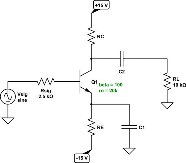
The schematic follows here:
schematic

simulate this circuit – Schematic created using CircuitLab


For part (a) you know to consider the signal voltage as \$0\:\textrm{V}\$ (quiescent) for the purposes of computing the value of \$R_E\$. I assume you know how to perform the usual KVL loop from the signal source to the \$-15\:\textrm{V}\$ source, as:

$$V_{sig}+I_B\cdot R_{sig}+V_{BE}+I_E\cdot R_E + \left(-15\:\textrm{V}\right)=0\:\textrm{V}$$

From that, and knowing that \$I_E=\left(\beta+1\right)\cdot I_B\$, it's easy to find:

$$\begin{align*} R_E&=\frac{15\:\textrm{V}-V_{sig}-\frac{I_E}{\beta+1}\cdot R_{sig}-V_{BE}}{I_E}\\\\ &=\frac{15\:\textrm{V}-\frac{500\:\mu\textrm{A}}{101}\cdot 2.5\:\textrm{k}\Omega-700\:\textrm{mV}}{500\:\mu\textrm{A}}\\\\ &= 28.5752475\:\textrm{k}\Omega \end{align*}$$

So I believe your teacher is right about this detail. \$R_E\approx 28.575\:\textrm{k}\Omega\$.


For part (b), you know the collector current is \$I_C=I_E\cdot\frac{100}{101}\approx 495\:\mu\textrm{A}\$. You also know that this collector current must drop \$10\:\textrm{V}\$ across \$R_C\$, so \$R_C=\frac{10\:\textrm{V}}{495\:\mu\textrm{A}}=20.2\:\textrm{k}\Omega\$, as you already surmised.


For part (c), you are now dealing with the AC voltage gain. What first bothered me with your given situation is \$r_o=20\:\textrm{k}\Omega\$. That's a crazy low number. Let's take the DC quiescent point and follow this logic through. We know that \$r_o=\frac{V_A+V_{CE}}{I_C}\$, but this means that \$V_A=I_C\cdot r_o-V_{CE}=495\:\mu\textrm{A}\cdot 20\:\textrm{k}\Omega-5.7\:\textrm{V}=4.2\:\textrm{V}\$. (Which is pretty much insane. I don't buy it. But I suppose it must be accepted as given.)

I have to assume some value for \$V_T\$, so I'll assume \$V_T\approx 25\:\textrm{mV}\$ for the following. Knowing that \$g_m=\frac{I_C}{V_T}\$ and \$r_\pi=\frac{\beta}{g_m}\$ and \$r_e=\frac{1}{g_m}\$ then the total gain should be:

$$\begin{align*} A_V&=\frac{r_\pi}{r_\pi+R_{sig}}\cdot\frac{R_C}{r_e}\cdot\frac{r_o}{r_o+R_C}\cdot\frac{R_L}{R_L+\left(r_o\vert\vert R_C\right)}\\\\ &=\frac{\frac{\beta}{g_m}}{\frac{\beta}{g_m}+R_{sig}}\cdot\frac{20.2\:\textrm{k}\Omega}{\frac{1}{g_m}}\cdot\frac{20\:\textrm{k}\Omega}{20\:\textrm{k}\Omega+20.2\:\textrm{k}\Omega}\cdot\frac{10\:\textrm{k}\Omega}{10\:\textrm{k}\Omega+\left(20\:\textrm{k}\Omega\vert\vert 20.2\:\textrm{k}\Omega\right)}\\\\ &=\frac{100}{100\cdot \frac{V_T}{I_C}+2.5\:\textrm{k}\Omega}\cdot 20.2\:\textrm{k}\Omega\cdot\frac{20\:\textrm{k}\Omega}{20\:\textrm{k}\Omega+20.2\:\textrm{k}\Omega}\cdot\frac{10\:\textrm{k}\Omega}{10\:\textrm{k}\Omega+\left(20\:\textrm{k}\Omega\vert\vert 20.2\:\textrm{k}\Omega\right)}\\\\ &\approx 66.385 \end{align*}$$$$\begin{align*} \vert A_V\vert &=\frac{r_\pi}{r_\pi+R_{sig}}\cdot\frac{R_C}{r_e}\cdot\frac{r_o}{r_o+R_C}\cdot\frac{R_L}{R_L+\left(r_o\vert\vert R_C\right)}\\\\ &=\frac{\frac{\beta}{g_m}}{\frac{\beta}{g_m}+R_{sig}}\cdot\frac{20.2\:\textrm{k}\Omega}{\frac{1}{g_m}}\cdot\frac{20\:\textrm{k}\Omega}{20\:\textrm{k}\Omega+20.2\:\textrm{k}\Omega}\cdot\frac{10\:\textrm{k}\Omega}{10\:\textrm{k}\Omega+\left(20\:\textrm{k}\Omega\vert\vert 20.2\:\textrm{k}\Omega\right)}\\\\ &=\frac{100}{100\cdot \frac{V_T}{I_C}+2.5\:\textrm{k}\Omega}\cdot 20.2\:\textrm{k}\Omega\cdot\frac{20\:\textrm{k}\Omega}{20\:\textrm{k}\Omega+20.2\:\textrm{k}\Omega}\cdot\frac{10\:\textrm{k}\Omega}{10\:\textrm{k}\Omega+\left(20\:\textrm{k}\Omega\vert\vert 20.2\:\textrm{k}\Omega\right)}\\\\ &\approx 66.385 \end{align*}$$

Close.

I still can't stomach the \$r_o\$ value you have. But that's what works out in the end, if you accept it as valid.

The schematic follows here:

schematic

simulate this circuit – Schematic created using CircuitLab


For part (a) you know to consider the signal voltage as \$0\:\textrm{V}\$ (quiescent) for the purposes of computing the value of \$R_E\$. I assume you know how to perform the usual KVL loop from the signal source to the \$-15\:\textrm{V}\$ source, as:

$$V_{sig}+I_B\cdot R_{sig}+V_{BE}+I_E\cdot R_E + \left(-15\:\textrm{V}\right)=0\:\textrm{V}$$

From that, and knowing that \$I_E=\left(\beta+1\right)\cdot I_B\$, it's easy to find:

$$\begin{align*} R_E&=\frac{15\:\textrm{V}-V_{sig}-\frac{I_E}{\beta+1}\cdot R_{sig}-V_{BE}}{I_E}\\\\ &=\frac{15\:\textrm{V}-\frac{500\:\mu\textrm{A}}{101}\cdot 2.5\:\textrm{k}\Omega-700\:\textrm{mV}}{500\:\mu\textrm{A}}\\\\ &= 28.5752475\:\textrm{k}\Omega \end{align*}$$

So I believe your teacher is right about this detail. \$R_E\approx 28.575\:\textrm{k}\Omega\$.


For part (b), you know the collector current is \$I_C=I_E\cdot\frac{100}{101}\approx 495\:\mu\textrm{A}\$. You also know that this collector current must drop \$10\:\textrm{V}\$ across \$R_C\$, so \$R_C=\frac{10\:\textrm{V}}{495\:\mu\textrm{A}}=20.2\:\textrm{k}\Omega\$, as you already surmised.


For part (c), you are now dealing with the AC voltage gain. What first bothered me with your given situation is \$r_o=20\:\textrm{k}\Omega\$. That's a crazy low number. Let's take the DC quiescent point and follow this logic through. We know that \$r_o=\frac{V_A+V_{CE}}{I_C}\$, but this means that \$V_A=I_C\cdot r_o-V_{CE}=495\:\mu\textrm{A}\cdot 20\:\textrm{k}\Omega-5.7\:\textrm{V}=4.2\:\textrm{V}\$. (Which is pretty much insane. I don't buy it. But I suppose it must be accepted as given.)

I have to assume some value for \$V_T\$, so I'll assume \$V_T\approx 25\:\textrm{mV}\$ for the following. Knowing that \$g_m=\frac{I_C}{V_T}\$ and \$r_\pi=\frac{\beta}{g_m}\$ and \$r_e=\frac{1}{g_m}\$ then the total gain should be:

$$\begin{align*} A_V&=\frac{r_\pi}{r_\pi+R_{sig}}\cdot\frac{R_C}{r_e}\cdot\frac{r_o}{r_o+R_C}\cdot\frac{R_L}{R_L+\left(r_o\vert\vert R_C\right)}\\\\ &=\frac{\frac{\beta}{g_m}}{\frac{\beta}{g_m}+R_{sig}}\cdot\frac{20.2\:\textrm{k}\Omega}{\frac{1}{g_m}}\cdot\frac{20\:\textrm{k}\Omega}{20\:\textrm{k}\Omega+20.2\:\textrm{k}\Omega}\cdot\frac{10\:\textrm{k}\Omega}{10\:\textrm{k}\Omega+\left(20\:\textrm{k}\Omega\vert\vert 20.2\:\textrm{k}\Omega\right)}\\\\ &=\frac{100}{100\cdot \frac{V_T}{I_C}+2.5\:\textrm{k}\Omega}\cdot 20.2\:\textrm{k}\Omega\cdot\frac{20\:\textrm{k}\Omega}{20\:\textrm{k}\Omega+20.2\:\textrm{k}\Omega}\cdot\frac{10\:\textrm{k}\Omega}{10\:\textrm{k}\Omega+\left(20\:\textrm{k}\Omega\vert\vert 20.2\:\textrm{k}\Omega\right)}\\\\ &\approx 66.385 \end{align*}$$

Close.

I still can't stomach the \$r_o\$ value you have. But that's what works out in the end, if you accept it as valid.

The schematic follows here:

schematic

simulate this circuit – Schematic created using CircuitLab


For part (a) you know to consider the signal voltage as \$0\:\textrm{V}\$ (quiescent) for the purposes of computing the value of \$R_E\$. I assume you know how to perform the usual KVL loop from the signal source to the \$-15\:\textrm{V}\$ source, as:

$$V_{sig}+I_B\cdot R_{sig}+V_{BE}+I_E\cdot R_E + \left(-15\:\textrm{V}\right)=0\:\textrm{V}$$

From that, and knowing that \$I_E=\left(\beta+1\right)\cdot I_B\$, it's easy to find:

$$\begin{align*} R_E&=\frac{15\:\textrm{V}-V_{sig}-\frac{I_E}{\beta+1}\cdot R_{sig}-V_{BE}}{I_E}\\\\ &=\frac{15\:\textrm{V}-\frac{500\:\mu\textrm{A}}{101}\cdot 2.5\:\textrm{k}\Omega-700\:\textrm{mV}}{500\:\mu\textrm{A}}\\\\ &= 28.5752475\:\textrm{k}\Omega \end{align*}$$

So I believe your teacher is right about this detail. \$R_E\approx 28.575\:\textrm{k}\Omega\$.


For part (b), you know the collector current is \$I_C=I_E\cdot\frac{100}{101}\approx 495\:\mu\textrm{A}\$. You also know that this collector current must drop \$10\:\textrm{V}\$ across \$R_C\$, so \$R_C=\frac{10\:\textrm{V}}{495\:\mu\textrm{A}}=20.2\:\textrm{k}\Omega\$, as you already surmised.


For part (c), you are now dealing with the AC voltage gain. What first bothered me with your given situation is \$r_o=20\:\textrm{k}\Omega\$. That's a crazy low number. Let's take the DC quiescent point and follow this logic through. We know that \$r_o=\frac{V_A+V_{CE}}{I_C}\$, but this means that \$V_A=I_C\cdot r_o-V_{CE}=495\:\mu\textrm{A}\cdot 20\:\textrm{k}\Omega-5.7\:\textrm{V}=4.2\:\textrm{V}\$. (Which is pretty much insane. I don't buy it. But I suppose it must be accepted as given.)

I have to assume some value for \$V_T\$, so I'll assume \$V_T\approx 25\:\textrm{mV}\$ for the following. Knowing that \$g_m=\frac{I_C}{V_T}\$ and \$r_\pi=\frac{\beta}{g_m}\$ and \$r_e=\frac{1}{g_m}\$ then the total gain should be:

$$\begin{align*} \vert A_V\vert &=\frac{r_\pi}{r_\pi+R_{sig}}\cdot\frac{R_C}{r_e}\cdot\frac{r_o}{r_o+R_C}\cdot\frac{R_L}{R_L+\left(r_o\vert\vert R_C\right)}\\\\ &=\frac{\frac{\beta}{g_m}}{\frac{\beta}{g_m}+R_{sig}}\cdot\frac{20.2\:\textrm{k}\Omega}{\frac{1}{g_m}}\cdot\frac{20\:\textrm{k}\Omega}{20\:\textrm{k}\Omega+20.2\:\textrm{k}\Omega}\cdot\frac{10\:\textrm{k}\Omega}{10\:\textrm{k}\Omega+\left(20\:\textrm{k}\Omega\vert\vert 20.2\:\textrm{k}\Omega\right)}\\\\ &=\frac{100}{100\cdot \frac{V_T}{I_C}+2.5\:\textrm{k}\Omega}\cdot 20.2\:\textrm{k}\Omega\cdot\frac{20\:\textrm{k}\Omega}{20\:\textrm{k}\Omega+20.2\:\textrm{k}\Omega}\cdot\frac{10\:\textrm{k}\Omega}{10\:\textrm{k}\Omega+\left(20\:\textrm{k}\Omega\vert\vert 20.2\:\textrm{k}\Omega\right)}\\\\ &\approx 66.385 \end{align*}$$

Close.

I still can't stomach the \$r_o\$ value you have. But that's what works out in the end, if you accept it as valid.

Source Link
jonk
  • 78.7k
  • 6
  • 81
  • 195

The schematic follows here:

schematic

simulate this circuit – Schematic created using CircuitLab


For part (a) you know to consider the signal voltage as \$0\:\textrm{V}\$ (quiescent) for the purposes of computing the value of \$R_E\$. I assume you know how to perform the usual KVL loop from the signal source to the \$-15\:\textrm{V}\$ source, as:

$$V_{sig}+I_B\cdot R_{sig}+V_{BE}+I_E\cdot R_E + \left(-15\:\textrm{V}\right)=0\:\textrm{V}$$

From that, and knowing that \$I_E=\left(\beta+1\right)\cdot I_B\$, it's easy to find:

$$\begin{align*} R_E&=\frac{15\:\textrm{V}-V_{sig}-\frac{I_E}{\beta+1}\cdot R_{sig}-V_{BE}}{I_E}\\\\ &=\frac{15\:\textrm{V}-\frac{500\:\mu\textrm{A}}{101}\cdot 2.5\:\textrm{k}\Omega-700\:\textrm{mV}}{500\:\mu\textrm{A}}\\\\ &= 28.5752475\:\textrm{k}\Omega \end{align*}$$

So I believe your teacher is right about this detail. \$R_E\approx 28.575\:\textrm{k}\Omega\$.


For part (b), you know the collector current is \$I_C=I_E\cdot\frac{100}{101}\approx 495\:\mu\textrm{A}\$. You also know that this collector current must drop \$10\:\textrm{V}\$ across \$R_C\$, so \$R_C=\frac{10\:\textrm{V}}{495\:\mu\textrm{A}}=20.2\:\textrm{k}\Omega\$, as you already surmised.


For part (c), you are now dealing with the AC voltage gain. What first bothered me with your given situation is \$r_o=20\:\textrm{k}\Omega\$. That's a crazy low number. Let's take the DC quiescent point and follow this logic through. We know that \$r_o=\frac{V_A+V_{CE}}{I_C}\$, but this means that \$V_A=I_C\cdot r_o-V_{CE}=495\:\mu\textrm{A}\cdot 20\:\textrm{k}\Omega-5.7\:\textrm{V}=4.2\:\textrm{V}\$. (Which is pretty much insane. I don't buy it. But I suppose it must be accepted as given.)

I have to assume some value for \$V_T\$, so I'll assume \$V_T\approx 25\:\textrm{mV}\$ for the following. Knowing that \$g_m=\frac{I_C}{V_T}\$ and \$r_\pi=\frac{\beta}{g_m}\$ and \$r_e=\frac{1}{g_m}\$ then the total gain should be:

$$\begin{align*} A_V&=\frac{r_\pi}{r_\pi+R_{sig}}\cdot\frac{R_C}{r_e}\cdot\frac{r_o}{r_o+R_C}\cdot\frac{R_L}{R_L+\left(r_o\vert\vert R_C\right)}\\\\ &=\frac{\frac{\beta}{g_m}}{\frac{\beta}{g_m}+R_{sig}}\cdot\frac{20.2\:\textrm{k}\Omega}{\frac{1}{g_m}}\cdot\frac{20\:\textrm{k}\Omega}{20\:\textrm{k}\Omega+20.2\:\textrm{k}\Omega}\cdot\frac{10\:\textrm{k}\Omega}{10\:\textrm{k}\Omega+\left(20\:\textrm{k}\Omega\vert\vert 20.2\:\textrm{k}\Omega\right)}\\\\ &=\frac{100}{100\cdot \frac{V_T}{I_C}+2.5\:\textrm{k}\Omega}\cdot 20.2\:\textrm{k}\Omega\cdot\frac{20\:\textrm{k}\Omega}{20\:\textrm{k}\Omega+20.2\:\textrm{k}\Omega}\cdot\frac{10\:\textrm{k}\Omega}{10\:\textrm{k}\Omega+\left(20\:\textrm{k}\Omega\vert\vert 20.2\:\textrm{k}\Omega\right)}\\\\ &\approx 66.385 \end{align*}$$

Close.

I still can't stomach the \$r_o\$ value you have. But that's what works out in the end, if you accept it as valid.