added 144 characters in body
Source Link
Blair Fonville
  • 4.1k
  • 4
  • 20
  • 47

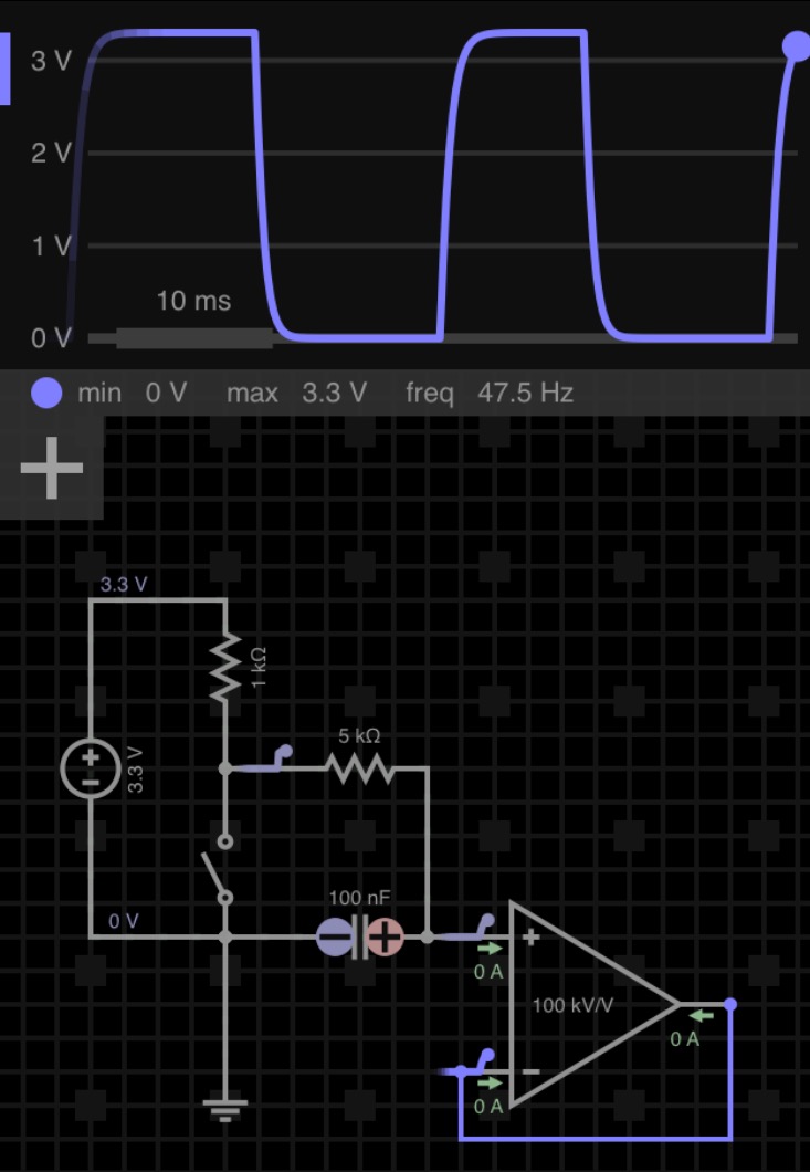
The first is the better option. Notice that the second circuit does not provide the output gate with the intended 0 V ground when the switch is closed. It is supplied a low level voltage through a voltage divider.

However, when the switch is closed in the first circuit, the gate's input is pulled down to ground, but slowly- as the cap discharges. This is what you want.

Edit also read all the comments. I agree with mkeith that, if this is for a microcontroller project, consider denouncing in firmware.

And jonk is right (as he often is) that there may be better, prepackaged, options depending on your needs.

Edit: 3.3 V will work fine with a 7414, provided you supply the IC with 5 V nominal on the VCC pin to power the chip. The resistors are up to you. The values of the resistors and capacitor affects the capacitor's charge/discharge time. Higher values provide more denouncing, but increase the wait time allowed between subsequent triggers. You might also want to add a voltage follower as an output stage.

For Example: Example circuit

and...

Regarding your 7414 question in the comments: 7414 Datasheet
The first is the better option. Notice that the second circuit does not provide the output gate with the intended 0 V ground when the switch is closed. It is supplied a low level voltage through a voltage divider.

However, when the switch is closed in the first circuit, the gate's input is pulled down to ground, but slowly- as the cap discharges. This is what you want.

Edit also read all the comments. I agree with mkeith that, if this is for a microcontroller project, consider denouncing in firmware.

And jonk is right (as he often is) that there may be better, prepackaged, options depending on your needs.

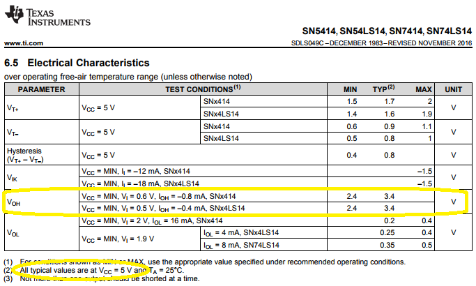
Edit: 3.3 V will work fine with a 7414, provided you supply the IC with 5 V nominal on the VCC pin to power the chip. The resistors are up to you. The values of the resistors and capacitor affects the capacitor's charge/discharge time. Higher values provide more denouncing, but increase the wait time allowed between subsequent triggers. You might also want to add a voltage follower as an output stage.

For Example: Example circuit

and...

Regarding your 7414 question in the comments: 7414 Datasheet

added 477 characters in body; added 21 characters in body
Source Link
Blair Fonville
  • 4.1k
  • 4
  • 20
  • 47

The first is the better option. Notice that the second circuit does not provide the output gate with the intended 0 V ground when the switch is closed. It is supplied a low level voltage through a voltage divider.

However, when the switch is closed in the first circuit, the gate's input is pulled down to ground, but slowly- as the cap discharges. This is what you want.

Edit also read all the comments. I agree with mkeith that, if this is for a microcontroller project, consider denouncing in firmware.

And jonk is right (as he often is) that there may be better, prepackaged, options depending on your needs.

Edit: 3.3 V will work fine with a 7414, provided you supply the IC with 5 V nominal on the VCC pin to power the chip. The resistors are up to you. The values of the resistors and capacitor affects the capacitor's charge/discharge time. Higher values provide more denouncing, but increase the wait time allowed between subsequent triggers. You might also want to add a voltage follower as an output stage.

For Example: Example circuit

The first is the better option. Notice that the second circuit does not provide the output gate with the intended 0 V ground when the switch is closed. It is supplied a low level voltage through a voltage divider.

However, when the switch is closed in the first circuit, the gate's input is pulled down to ground, but slowly- as the cap discharges. This is what you want.

Edit also read all the comments. I agree with mkeith that, if this is for a microcontroller project, consider denouncing in firmware.

And jonk is right (as he often is) that there may be better, prepackaged, options depending on your needs.

Edit: 3.3 V will work fine with a 7414, provided you supply the IC with 5 V nominal on the VCC pin to power the chip. The resistors are up to you. The values of the resistors and capacitor affects the capacitor's charge/discharge time. Higher values provide more denouncing, but increase the wait time allowed between subsequent triggers. You might also want to add a voltage follower as an output stage.

For Example: Example circuit

added 108 characters in body; added 2 characters in body
Source Link
Blair Fonville
  • 4.1k
  • 4
  • 20
  • 47

The first is the better option. Notice that the second circuit does not provide the output gate with the intended 0 V ground when the switch is closed. It is supplied a low level voltage through a voltage divider.

However, when the switch is closed in the first circuit, the gate's input is pulled down to ground, but slowly- as the cap discharges. This is what you want.

Edit also read all the comments. I agree with mkeith that, if this is for a microcontroller project, consider denouncing in firmware.

And jonk is right (as he often is) that there may be better, prepackaged, options depending on your needs.

The first is the better option. Notice that the second circuit does not provide the output gate with the intended 0 V ground when the switch is closed. It is supplied a low level voltage through a voltage divider.

However, when the switch is closed in the first circuit, the gate's input is pulled down to ground, but slowly- as the cap discharges. This is what you want.

Edit also read all the comments. I agree with mkeith that, if this is for a microcontroller project, consider denouncing in firmware.

And jonk is right (as he often is) that there may be better, prepackaged, options depending on your needs.

added 139 characters in body; deleted 2 characters in body; added 2 characters in body
Source Link
Blair Fonville
  • 4.1k
  • 4
  • 20
  • 47
Loading
Source Link
Blair Fonville
  • 4.1k
  • 4
  • 20
  • 47
Loading