added 2 characters in body
Source Link
Harry Svensson
  • 8.2k
  • 3
  • 34
  • 53

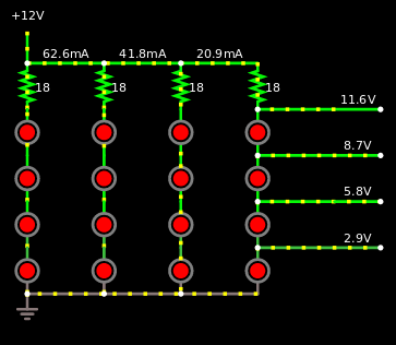
if I were you I would make something like this:

enter image description here

Here's a link if you want to play around


EDIT

I reread your question and saw that you said the LED strips needed 12V. That it was not your battery that delivered that. Your battery delivered 4.2V - 3.2V.

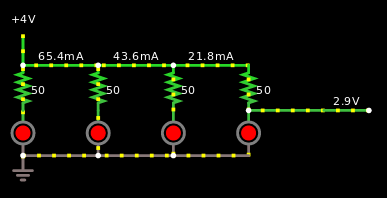
In that case this schematic would be much more viable:

enter image description here

Here's a link if you want to play around


Let's compare how bad it is to use current limiting resistors instead of using a buck converter or boost converter. Assume that a X converter is 80% efficient. Let's also assume that you will use 4 LED's like in the schematic above.

\$P = VI\$
\$P_{LED} = 4(3.3×0.02) = 264 mW\$ the 4 comes from 4 LED's

With a boost converter you'd get this equation:
\$P_{w/converter}=\frac{P_{LED}}{0.8} = \frac{264}{0.8} = 330 mW\$\$P_{w/converter}=\frac{P_{LED}}{0.8} = \frac{0.264}{0.8} = 330 mW\$

With 50 ohm resistor per lane like in the schematic it would become like this: \$P_{w/resistor} = I^2R + P_{LED} = 4(0.02^2×50)+0.264 = 344mW\$

\$\frac{344}{330}=104\%\$ So if you use a constant current boost converter that is 80% efficient instead of 50 ohm resistors, then you'll be 4% more efficient. It will be the same story if you use more LED's, the 4% that is. But if you however get a constant current boost converter that is more efficient than 80%.. then that one will turn the 4% to like 20% and then it might be more viable.

if I were you I would make something like this:

enter image description here

Here's a link if you want to play around


EDIT

I reread your question and saw that you said the LED strips needed 12V. That it was not your battery that delivered that. Your battery delivered 4.2V - 3.2V.

In that case this schematic would be much more viable:

enter image description here

Here's a link if you want to play around


Let's compare how bad it is to use current limiting resistors instead of using a buck converter or boost converter. Assume that a X converter is 80% efficient. Let's also assume that you will use 4 LED's like in the schematic above.

\$P = VI\$
\$P_{LED} = 4(3.3×0.02) = 264 mW\$ the 4 comes from 4 LED's

With a boost converter you'd get this equation:
\$P_{w/converter}=\frac{P_{LED}}{0.8} = \frac{264}{0.8} = 330 mW\$

With 50 ohm resistor per lane like in the schematic it would become like this: \$P_{w/resistor} = I^2R + P_{LED} = 4(0.02^2×50)+0.264 = 344mW\$

\$\frac{344}{330}=104\%\$ So if you use a constant current boost converter that is 80% efficient instead of 50 ohm resistors, then you'll be 4% more efficient. It will be the same story if you use more LED's, the 4% that is. But if you however get a constant current boost converter that is more efficient than 80%.. then that one will turn the 4% to like 20% and then it might be more viable.
if I were you I would make something like this:

enter image description here

Here's a link if you want to play around


EDIT

I reread your question and saw that you said the LED strips needed 12V. That it was not your battery that delivered that. Your battery delivered 4.2V - 3.2V.

In that case this schematic would be much more viable:

enter image description here

Here's a link if you want to play around


Let's compare how bad it is to use current limiting resistors instead of using a buck converter or boost converter. Assume that a X converter is 80% efficient. Let's also assume that you will use 4 LED's like in the schematic above.

\$P = VI\$
\$P_{LED} = 4(3.3×0.02) = 264 mW\$ the 4 comes from 4 LED's

With a boost converter you'd get this equation:
\$P_{w/converter}=\frac{P_{LED}}{0.8} = \frac{0.264}{0.8} = 330 mW\$

With 50 ohm resistor per lane like in the schematic it would become like this: \$P_{w/resistor} = I^2R + P_{LED} = 4(0.02^2×50)+0.264 = 344mW\$

\$\frac{344}{330}=104\%\$ So if you use a constant current boost converter that is 80% efficient instead of 50 ohm resistors, then you'll be 4% more efficient. It will be the same story if you use more LED's, the 4% that is. But if you however get a constant current boost converter that is more efficient than 80%.. then that one will turn the 4% to like 20% and then it might be more viable.

Reread the question and made it appropriate, 4V input, not 12V.
Source Link
Harry Svensson
  • 8.2k
  • 3
  • 34
  • 53

if I were you I would make something like this:

enter image description here

Here's a link if you want to play around


EDIT

I reread your question and saw that you said the LED strips needed 12V. That it was not your battery that delivered that. Your battery delivered 4.2V - 3.2V.

In that case this schematic would be much more viable:

enter image description here

Here's a link if you want to play around


Let's compare how bad it is to use current limiting resistors instead of using a buck converter or boost converter. Assume that a X converter is 80% efficient. Let's also assume that you will use 4 LED's like in the schematic above.

\$P = VI\$
\$P_{LED} = 4(3.3×0.02) = 264 mW\$ the 4 comes from 4 LED's

With a boost converter you'd get this equation:
\$P_{w/converter}=\frac{P_{LED}}{0.8} = \frac{264}{0.8} = 330 mW\$

With 50 ohm resistor per lane like in the schematic it would become like this: \$P_{w/resistor} = I^2R + P_{LED} = 4(0.02^2×50)+0.264 = 344mW\$

\$\frac{344}{330}=104\%\$ So if you use a constant current boost converter that is 80% efficient instead of 50 ohm resistors, then you'll be 4% more efficient. It will be the same story if you use more LED's, the 4% that is. But if you however get a constant current boost converter that is more efficient than 80%.. then that one will turn the 4% to like 20% and then it might be more viable.

if I were you I would make something like this:

enter image description here

Here's a link if you want to play around


EDIT

I reread your question and saw that you said the LED strips needed 12V. That it was not your battery that delivered that. Your battery delivered 4.2V - 3.2V.

In that case this schematic would be much more viable:

enter image description here

Here's a link if you want to play around


Let's compare how bad it is to use current limiting resistors instead of using a buck converter or boost converter. Assume that a X converter is 80% efficient. Let's also assume that you will use 4 LED's like in the schematic above.

\$P = VI\$
\$P_{LED} = 4(3.3×0.02) = 264 mW\$ the 4 comes from 4 LED's

With a boost converter you'd get this equation:
\$P_{w/converter}=\frac{P_{LED}}{0.8} = \frac{264}{0.8} = 330 mW\$

With 50 ohm resistor per lane like in the schematic it would become like this: \$P_{w/resistor} = I^2R + P_{LED} = 4(0.02^2×50)+0.264 = 344mW\$

\$\frac{344}{330}=104\%\$ So if you use a constant current boost converter that is 80% efficient instead of 50 ohm resistors, then you'll be 4% more efficient. It will be the same story if you use more LED's, the 4% that is. But if you however get a constant current boost converter that is more efficient than 80%.. then that one will turn the 4% to like 20% and then it might be more viable.

Reread the question and made it appropriate, 4V input, not 12V.
Source Link
Harry Svensson
  • 8.2k
  • 3
  • 34
  • 53

if I were you I would make something like this:

enter image description here

Here's a link if you want to play around


EDIT

I reread your question and saw that you said the LED strips needed 12V. That it was not your battery that delivered that. Your battery delivered 4.2V - 3.2V.

In that case this schematic would be much more viable:

enter image description here

Here's a link if you want to play around

if I were you I would make something like this:

enter image description here

Here's a link if you want to play around

if I were you I would make something like this:

enter image description here

Here's a link if you want to play around


EDIT

I reread your question and saw that you said the LED strips needed 12V. That it was not your battery that delivered that. Your battery delivered 4.2V - 3.2V.

In that case this schematic would be much more viable:

enter image description here

Here's a link if you want to play around

Source Link
Harry Svensson
  • 8.2k
  • 3
  • 34
  • 53
Loading