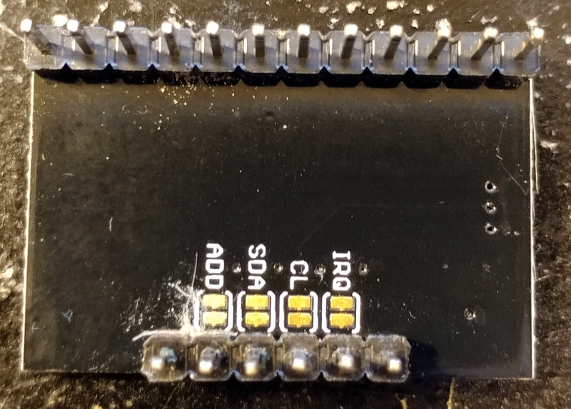
I've been trying to setup two MPR121 capacitive touch sensors and from what I understand, I need to cut the PCB trace between the ADD and GND pins. I've tried scrappingscraping off a bit between them on the top side of the PCB, but they still are showing being connected on my multimeter. Where is the proper location on these PCBs for cutting this trace?
Update: The module in question is a XO MPR121 Breakout
The product page has a view of the front, below is a picture I took of the back:
I see now on a product page it mentions the jumpers. I assume these are the pairs of contact pads on the back side?. So do I need to cut a trace in between the pair next to ADD and then connect ADD to say SDA with a wire?

