typo
Source Link
nettek
  • 1.1k
  • 4
  • 15
  • 24

I think an easier way would be to useruse a pull-up resistor:
schematic

simulate this circuit – Schematic created using CircuitLab

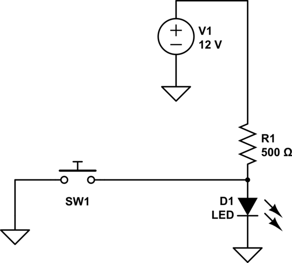
When the switch is "off" (open, like displayed in the schematic), the voltage source provides current to the led through the resistor, so it turns it on. Assuming the LED's forward voltage is 2V, forward current is 20mA, the calculation for the resistor is as following:

V1 = I*R1 + Vf

R1 = (V1 - Vf)/I = (12-2)/20m = 500Ohm

When the switch is "on" (closed), the current provided by the voltage source V1 flows to ground, so the LED does not turn on. Or you can think of it as the anode of the LED having 0V, like it's cathode, therefore not turning on.

I think an easier way would be to user a pull-up resistor:

schematic

simulate this circuit – Schematic created using CircuitLab

When the switch is "off" (open, like displayed in the schematic), the voltage source provides current to the led through the resistor, so it turns it on. Assuming the LED's forward voltage is 2V, forward current is 20mA, the calculation for the resistor is as following:

V1 = I*R1 + Vf

R1 = (V1 - Vf)/I = (12-2)/20m = 500Ohm

When the switch is "on" (closed), the current provided by the voltage source V1 flows to ground, so the LED does not turn on. Or you can think of it as the anode of the LED having 0V, like it's cathode, therefore not turning on.

I think an easier way would be to use a pull-up resistor:

schematic

simulate this circuit – Schematic created using CircuitLab

When the switch is "off" (open, like displayed in the schematic), the voltage source provides current to the led through the resistor, so it turns it on. Assuming the LED's forward voltage is 2V, forward current is 20mA, the calculation for the resistor is as following:

V1 = I*R1 + Vf

R1 = (V1 - Vf)/I = (12-2)/20m = 500Ohm

When the switch is "on" (closed), the current provided by the voltage source V1 flows to ground, so the LED does not turn on. Or you can think of it as the anode of the LED having 0V, like it's cathode, therefore not turning on.

Source Link
nettek
  • 1.1k
  • 4
  • 15
  • 24

I think an easier way would be to user a pull-up resistor:

schematic

simulate this circuit – Schematic created using CircuitLab

When the switch is "off" (open, like displayed in the schematic), the voltage source provides current to the led through the resistor, so it turns it on. Assuming the LED's forward voltage is 2V, forward current is 20mA, the calculation for the resistor is as following:

V1 = I*R1 + Vf

R1 = (V1 - Vf)/I = (12-2)/20m = 500Ohm

When the switch is "on" (closed), the current provided by the voltage source V1 flows to ground, so the LED does not turn on. Or you can think of it as the anode of the LED having 0V, like it's cathode, therefore not turning on.