added 224 characters in body
Source Link
Gerry
  • 15
  • 5

I am looking at using two p-ch MOSFETs in series as part of a high-side load switching scheme, and do not understand the following circuit behaviour.

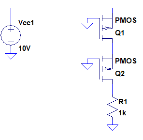
In simulation of the simplified schematic below, no current is driven into the load:

enter image description here

Edit: The MOSFETs being modelled are DMP2008UFG, model supplied by manufacturer

If neither Q1 or Q2 are conducting, Q2 has a floating source voltage and therefore undefined Vgs.

What I expected to happen:

  • Q1 to turn on, as its Vgs > Vth.
  • As Q1 is on, then Q2's source if no longer floating and is instead defined at near Vcc.
  • As Q2's Vgs>Vcc, Q2 conducts
  • Current flows into the load

Clearly I am misunderstanding the circuit. Why does no current flow into the load?

Many thanks in advance,

Gerry

I am looking at using two p-ch MOSFETs in series as part of a high-side load switching scheme, and do not understand the following circuit behaviour.

In simulation of the simplified schematic below, no current is driven into the load:

enter image description here

If neither Q1 or Q2 are conducting, Q2 has a floating source voltage and therefore undefined Vgs.

What I expected to happen:

  • Q1 to turn on, as its Vgs > Vth.
  • As Q1 is on, then Q2's source if no longer floating and is instead defined at near Vcc.
  • As Q2's Vgs>Vcc, Q2 conducts
  • Current flows into the load

Clearly I am misunderstanding the circuit. Why does no current flow into the load?

Many thanks in advance,

Gerry
I am looking at using two p-ch MOSFETs in series as part of a high-side load switching scheme, and do not understand the following circuit behaviour.

In simulation of the simplified schematic below, no current is driven into the load:

enter image description here

Edit: The MOSFETs being modelled are DMP2008UFG, model supplied by manufacturer

If neither Q1 or Q2 are conducting, Q2 has a floating source voltage and therefore undefined Vgs.

What I expected to happen:

  • Q1 to turn on, as its Vgs > Vth.
  • As Q1 is on, then Q2's source if no longer floating and is instead defined at near Vcc.
  • As Q2's Vgs>Vcc, Q2 conducts
  • Current flows into the load

Clearly I am misunderstanding the circuit. Why does no current flow into the load?

Many thanks in advance,

Gerry

Source Link
Gerry
  • 15
  • 5

Using series P-Channel MOSFETs for high-side switching

I am looking at using two p-ch MOSFETs in series as part of a high-side load switching scheme, and do not understand the following circuit behaviour.

In simulation of the simplified schematic below, no current is driven into the load:

enter image description here

If neither Q1 or Q2 are conducting, Q2 has a floating source voltage and therefore undefined Vgs.

What I expected to happen:

  • Q1 to turn on, as its Vgs > Vth.
  • As Q1 is on, then Q2's source if no longer floating and is instead defined at near Vcc.
  • As Q2's Vgs>Vcc, Q2 conducts
  • Current flows into the load

Clearly I am misunderstanding the circuit. Why does no current flow into the load?

Many thanks in advance,

Gerry