edited body
Source Link
Andy aka
  • 472.9k
  • 29
  • 383
  • 839

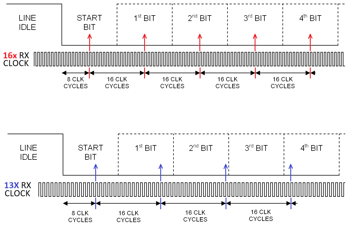
UART timing for asynchronous data relies on knowledge of the data rate and having a clock that is typically 16 x faster. The top half of the picture shows how data is re-synchronised and the bottom half shows a badly synchronised system (13x clock rate) just as an example: -

enter image description hereenter image description here

In the absense of any data edges, the correctly timed clock can sample the data pretty much at the middle of the symbol. In the lower picture, and without data edges to retime things, the 13x clock will eventually make an error.

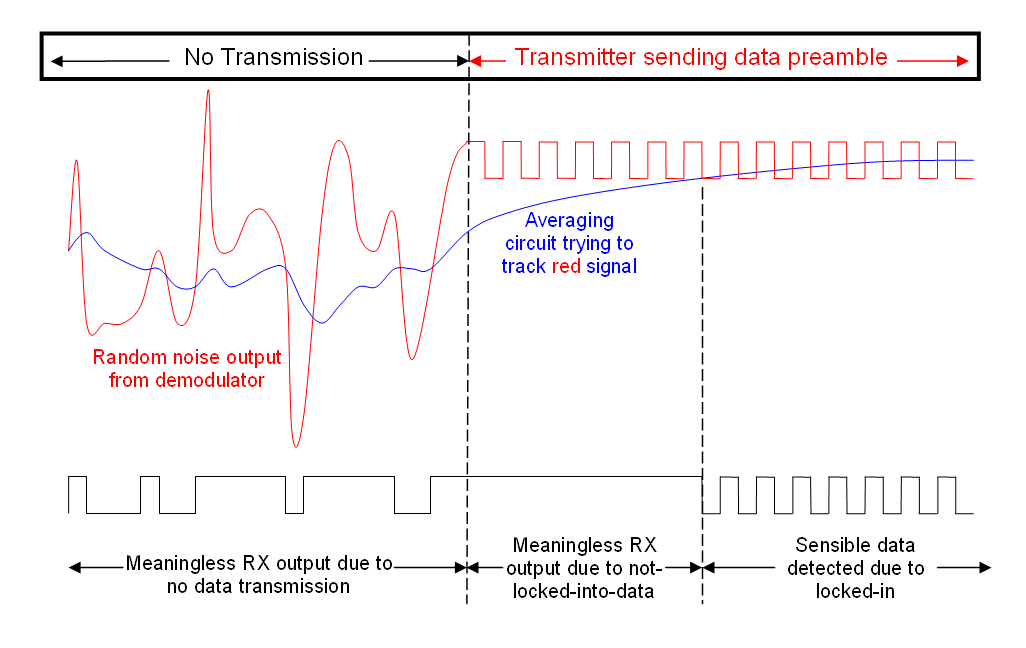
For the bigger "radio picture" you have to send a preamble to get things started i.e. you can't just hope to get lock straight away because there are many factors involved. Here's a picture I drew some time ago that explains how a preamble would work on a simple FM radio transmitter and receiver: -

enter image description here

And here is the previous answer that included that diagram. More useful information contained.

UART timing for asynchronous data relies on knowledge of the data rate and having a clock that is typically 16 x faster. The top half of the picture shows how data is re-synchronised and the bottom half shows a badly synchronised system (13x clock rate) just as an example: -

enter image description here

In the absense of any data edges, the correctly timed clock can sample the data pretty much at the middle of the symbol. In the lower picture, and without data edges to retime things, the 13x clock will eventually make an error.

For the bigger "radio picture" you have to send a preamble to get things started i.e. you can't just hope to get lock straight away because there are many factors involved. Here's a picture I drew some time ago that explains how a preamble would work on a simple FM radio transmitter and receiver: -

enter image description here

And here is the previous answer that included that diagram. More useful information contained.

UART timing for asynchronous data relies on knowledge of the data rate and having a clock that is typically 16 x faster. The top half of the picture shows how data is re-synchronised and the bottom half shows a badly synchronised system (13x clock rate) just as an example: -

enter image description here

In the absense of any data edges, the correctly timed clock can sample the data pretty much at the middle of the symbol. In the lower picture, and without data edges to retime things, the 13x clock will eventually make an error.

For the bigger "radio picture" you have to send a preamble to get things started i.e. you can't just hope to get lock straight away because there are many factors involved. Here's a picture I drew some time ago that explains how a preamble would work on a simple FM radio transmitter and receiver: -

enter image description here

And here is the previous answer that included that diagram. More useful information contained.
added 591 characters in body
Source Link
Andy aka
  • 472.9k
  • 29
  • 383
  • 839

UART timing for asynchronous data relies on knowledge of the data rate and having a clock that is typically 16 x faster. The top half of the picture shows how data is re-synchronised and the bottom half shows a badly synchronised system (13x clock rate) just as an example: -

enter image description here

In the absense of any data edges, the correctly timed clock can sample the data pretty much at the middle of the symbol. In the lower picture, and without data edges to retime things, the 13x clock will eventually make an error.

For the bigger "radio picture" you have to send a preamble to get things started i.e. you can't just hope to get lock straight away because there are many factors involved. Here's a picture I drew some time ago that explains how a preamble would work on a simple FM radio transmitter and receiver: -

enter image description here

And here is the previous answer that included that diagram. More useful information contained.
UART timing for asynchronous data relies on knowledge of the data rate and having a clock that is typically 16 x faster. The top half of the picture shows how data is re-synchronised and the bottom half shows a badly synchronised system (13x clock rate) just as an example: -

enter image description here

In the absense of any data edges, the correctly timed clock can sample the data pretty much at the middle of the symbol. In the lower picture, and without data edges to retime the 13x clock will eventually make an error.

UART timing for asynchronous data relies on knowledge of the data rate and having a clock that is typically 16 x faster. The top half of the picture shows how data is re-synchronised and the bottom half shows a badly synchronised system (13x clock rate) just as an example: -

enter image description here

In the absense of any data edges, the correctly timed clock can sample the data pretty much at the middle of the symbol. In the lower picture, and without data edges to retime things, the 13x clock will eventually make an error.

For the bigger "radio picture" you have to send a preamble to get things started i.e. you can't just hope to get lock straight away because there are many factors involved. Here's a picture I drew some time ago that explains how a preamble would work on a simple FM radio transmitter and receiver: -

enter image description here

And here is the previous answer that included that diagram. More useful information contained.

Source Link
Andy aka
  • 472.9k
  • 29
  • 383
  • 839

UART timing for asynchronous data relies on knowledge of the data rate and having a clock that is typically 16 x faster. The top half of the picture shows how data is re-synchronised and the bottom half shows a badly synchronised system (13x clock rate) just as an example: -

enter image description here

In the absense of any data edges, the correctly timed clock can sample the data pretty much at the middle of the symbol. In the lower picture, and without data edges to retime the 13x clock will eventually make an error.