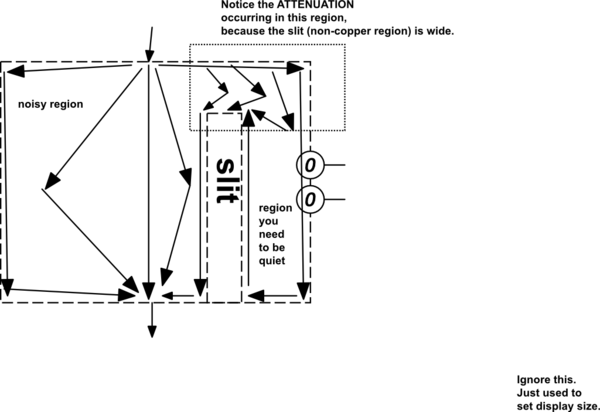
outlined the attenuation occuring because the slit/slot is WIDE
Source Link
analogsystemsrf
  • 35k
  • 2
  • 20
  • 48

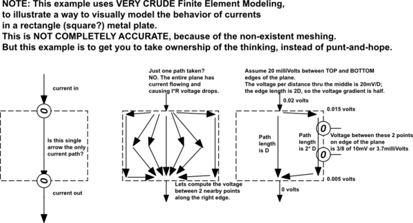
A plane has problems. Example
schematic

simulate this circuit – Schematic created using CircuitLab

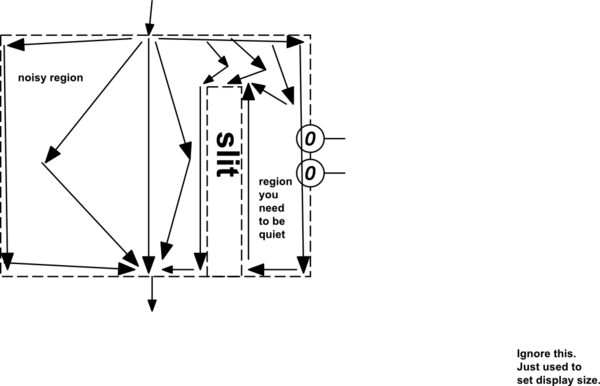
When you expect certain (hopefully nearby) nodes of the Ground Plane to have ZERO volts between those two nodes, that will not happen. Slits can be your friend, to reduce the interfering currents passing along the path between your two sensitive nodes.
schematicschematic

simulate this circuitsimulate this circuit

Take a copy of the schematic, printed out, and draw ALL the ground currents. Label their values and frequencies and edge-rates. (inductance may matter).

Now start planning how to keep the noise currents away from the GROUND nodes of your sensitive (feedback voltage dividers) circuits.

Note how WIDE slits provide more attenuation of bothersome currents.

My thinking on planes, tho I've done many fast circuits on planes at moderate fidelity, concerned the need for extreme fidelity for audio/music signals and for low-frequency 20/24 bit measurements. Thus LOW FREQUENCY thinking.

[oh Magnetic and Electric fields also matter]

A plane has problems. Example

schematic

simulate this circuit – Schematic created using CircuitLab

When you expect certain (hopefully nearby) nodes of the Ground Plane to have ZERO volts between those two nodes, that will not happen. Slits can be your friend, to reduce the interfering currents passing along the path between your two sensitive nodes.

schematic

simulate this circuit

Take a copy of the schematic, printed out, and draw ALL the ground currents. Label their values and frequencies and edge-rates. (inductance may matter).

Now start planning how to keep the noise currents away from the GROUND nodes of your sensitive (feedback voltage dividers) circuits.

Note how WIDE slits provide more attenuation of bothersome currents.

My thinking on planes, tho I've done many fast circuits on planes at moderate fidelity, concerned the need for extreme fidelity for audio/music signals and for low-frequency 20/24 bit measurements. Thus LOW FREQUENCY thinking.

[oh Magnetic and Electric fields also matter]
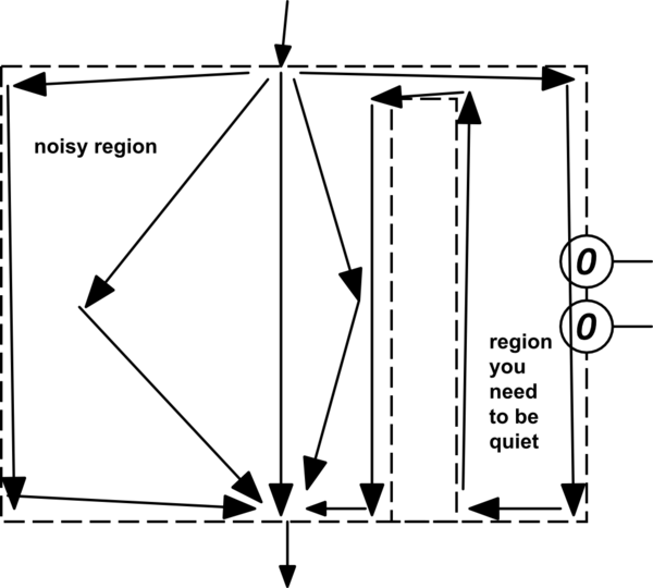
A plane has problems. Example

schematic

simulate this circuit – Schematic created using CircuitLab

When you expect certain (hopefully nearby) nodes of the Ground Plane to have ZERO volts between those two nodes, that will not happen. Slits can be your friend, to reduce the interfering currents passing along the path between your two sensitive nodes.

schematic

simulate this circuit

Take a copy of the schematic, printed out, and draw ALL the ground currents. Label their values and frequencies and edge-rates. (inductance may matter).

Now start planning how to keep the noise currents away from the GROUND nodes of your sensitive (feedback voltage dividers) circuits.

Note how WIDE slits provide more attenuation of bothersome currents.

My thinking on planes, tho I've done many fast circuits on planes at moderate fidelity, concerned the need for extreme fidelity for audio/music signals and for low-frequency 20/24 bit measurements. Thus LOW FREQUENCY thinking.

[oh Magnetic and Electric fields also matter]

added 230 characters in body
Source Link
analogsystemsrf
  • 35k
  • 2
  • 20
  • 48

A plane has problems. Example

schematic

simulate this circuit – Schematic created using CircuitLab

When you expect certain (hopefully nearby) nodes of the Ground Plane to have ZERO volts between those two nodes, that will not happen. Slits can be your friend, to reduce the interfering currents passing along the path between your two sensitive nodes.

schematic

simulate this circuit

Take a copy of the schematic, printed out, and draw ALL the ground currents. Label their values and frequencies and edge-rates. (inductance may matter).

Now start planning how to keep the noise currents away from the GROUND nodes of your sensitive (feedback voltage dividers) circuits.

Note how WIDE slits provide more attenuation of bothersome currents.

My thinking on planes, tho I've done many fast circuits on planes at moderate fidelity, concerned the need for extreme fidelity for audio/music signals and for low-frequency 20/24 bit measurements. Thus LOW FREQUENCY thinking.

[oh Magnetic and Electric fields also matter]

A plane has problems. Example

schematic

simulate this circuit – Schematic created using CircuitLab

When you expect certain (hopefully nearby) nodes of the Ground Plane to have ZERO volts between those two nodes, that will not happen. Slits can be your friend, to reduce the interfering currents passing along the path between your two sensitive nodes.

schematic

simulate this circuit

Take a copy of the schematic, printed out, and draw ALL the ground currents. Label their values and frequencies and edge-rates. (inductance may matter).

Now start planning how to keep the noise currents away from the GROUND nodes of your sensitive (feedback voltage dividers) circuits.

Note how WIDE slits provide more attenuation of bothersome currents.

My thinking on planes, tho I've done many fast circuits on planes at moderate fidelity, concerned the need for extreme fidelity for audio/music signals and for low-frequency 20/24 bit measurements. Thus LOW FREQUENCY thinking.

[oh Magnetic and Electric fields also matter]

added 864 characters in body
Source Link
analogsystemsrf
  • 35k
  • 2
  • 20
  • 48

A plane has problems. Example

schematic

simulate this circuit – Schematic created using CircuitLab

When you expect certain (hopefully nearby) nodes of the Ground Plane to have ZERO volts between those two nodes, that will not happen. Slits can be your friend, to preventreduce the interfering currents passing along the path between your two sensitive nodes.

schematicschematic

simulate this circuitsimulate this circuit

Take a copy of the schematic, printed out, and draw ALL the ground currents. Label their values and frequencies and edge-rates. (inductance may matter).

Now start planning how to keep the noise currents away from the GROUND nodes of your sensitive (feedback voltage dividers) circuits.

Note how WIDE slits provide more attenuation of bothersome currents.

[oh Magnetic and Electric fields also matter]

A plane has problems. Example

schematic

simulate this circuit – Schematic created using CircuitLab

When you expect certain (hopefully nearby) nodes of the Ground Plane to have ZERO volts between those two nodes, that will not happen. Slits can be your friend, to prevent the interfering currents passing along the path between your two sensitive nodes.

schematic

simulate this circuit

Take a copy of the schematic, printed out, and draw ALL the ground currents. Label their values and frequencies and edge-rates. (inductance may matter).

Now start planning how to keep the noise currents away from the GROUND nodes of your sensitive (feedback voltage dividers) circuits.

[oh Magnetic and Electric fields also matter]

A plane has problems. Example

schematic

simulate this circuit – Schematic created using CircuitLab

When you expect certain (hopefully nearby) nodes of the Ground Plane to have ZERO volts between those two nodes, that will not happen. Slits can be your friend, to reduce the interfering currents passing along the path between your two sensitive nodes.

schematic

simulate this circuit

Take a copy of the schematic, printed out, and draw ALL the ground currents. Label their values and frequencies and edge-rates. (inductance may matter).

Now start planning how to keep the noise currents away from the GROUND nodes of your sensitive (feedback voltage dividers) circuits.

Note how WIDE slits provide more attenuation of bothersome currents.

[oh Magnetic and Electric fields also matter]

added 864 characters in body
Source Link
analogsystemsrf
  • 35k
  • 2
  • 20
  • 48
Loading
Source Link
analogsystemsrf
  • 35k
  • 2
  • 20
  • 48
Loading