added 134 characters in body
Source Link
Ale..chenski
  • 42.4k
  • 3
  • 44
  • 113

The standalone circuit on page 36, Fig.41, has one missing connection, pin SYSOFF. This seems to be the datasheet mistake.

enter image description here

The spec says about SYSOFF pin:

System Enable Input. Connect SYSOFF high to turn off the FET connecting the battery to the system output. When an adapter is connected, charging is also disabled. Connect SYSOFF low for normal operation. SYSOFF is internally pulled up to VBAT through a large resistor (approximately 5 MΩ). Do not leave SYSOFF unconnected to ensure proper operation.

SO it looks like the transitor Q2 (see functional diagram section 9.2) is floating, partially open, which causes the voltage to drop.

Connect the SYSOFF to ground for proper operations.

The standalone circuit on page 36, Fig.41, has one missing connection, pin SYSOFF. The spec says about SYSOFF pin:

System Enable Input. Connect SYSOFF high to turn off the FET connecting the battery to the system output. When an adapter is connected, charging is also disabled. Connect SYSOFF low for normal operation. SYSOFF is internally pulled up to VBAT through a large resistor (approximately 5 MΩ). Do not leave SYSOFF unconnected to ensure proper operation.

SO it looks like the transitor Q2 (see functional diagram section 9.2) is floating, partially open, which causes the voltage to drop.

Connect the SYSOFF to ground for proper operations.
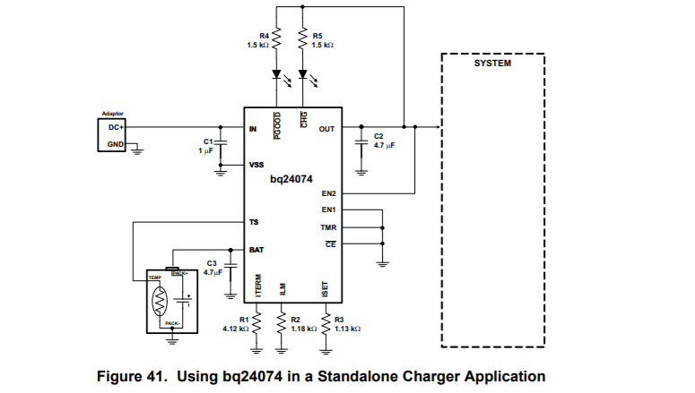
The standalone circuit on page 36, Fig.41, has one missing connection, pin SYSOFF. This seems to be the datasheet mistake.

enter image description here

The spec says about SYSOFF pin:

System Enable Input. Connect SYSOFF high to turn off the FET connecting the battery to the system output. When an adapter is connected, charging is also disabled. Connect SYSOFF low for normal operation. SYSOFF is internally pulled up to VBAT through a large resistor (approximately 5 MΩ). Do not leave SYSOFF unconnected to ensure proper operation.

SO it looks like the transitor Q2 (see functional diagram section 9.2) is floating, partially open, which causes the voltage to drop.

Connect the SYSOFF to ground for proper operations.

Source Link
Ale..chenski
  • 42.4k
  • 3
  • 44
  • 113

The standalone circuit on page 36, Fig.41, has one missing connection, pin SYSOFF. The spec says about SYSOFF pin:

System Enable Input. Connect SYSOFF high to turn off the FET connecting the battery to the system output. When an adapter is connected, charging is also disabled. Connect SYSOFF low for normal operation. SYSOFF is internally pulled up to VBAT through a large resistor (approximately 5 MΩ). Do not leave SYSOFF unconnected to ensure proper operation.

SO it looks like the transitor Q2 (see functional diagram section 9.2) is floating, partially open, which causes the voltage to drop.

Connect the SYSOFF to ground for proper operations.