Added two specific MOSFET options (suggested by @stevenvh)
Source Link

enter image description here

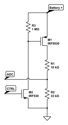
This seems to be very similar to Nick's schematic, was probably busy drawing it when he posted :-).

First why you can't use the N-FET on the high side: it needs a gate voltage a few volts higher than the source, and the 4.2 V is all you have, nothing higher, so that won't work.

I have a higher value for the pull-up, though a value of 100 kΩ also will do. 10 kΩ will cause an unnecessary extra current of 400 µA when you're measuring. Not the end of the world, but it's 1 resistor in both cases, so why not use a higher value.

For the MOSFETs, there are a variety of parts to choose from given the requirements are not so strict; you can consider inexpensive ones such as, e.g., Si2303 for the P-channel and BSS138 for the N-channel.

enter image description here

This seems to be very similar to Nick's schematic, was probably busy drawing it when he posted :-).

First why you can't use the N-FET on the high side: it needs a gate voltage a few volts higher than the source, and the 4.2 V is all you have, nothing higher, so that won't work.

I have a higher value for the pull-up, though a value of 100 kΩ also will do. 10 kΩ will cause an unnecessary extra current of 400 µA when you're measuring. Not the end of the world, but it's 1 resistor in both cases, so why not use a higher value.

For the MOSFETs, there are a variety of parts to choose from given the requirements are not so strict; you can consider inexpensive ones such as, e.g., Si2303 for the P-channel and BSS138 for the N-channel.

added 270 characters in body
Source Link
stevenvh
  • 146.6k
  • 21
  • 460
  • 669

enter image description here

This seems to be very similar to Nick's schematic, was probably busy drawing it when he posted :-).

First why you can't use the N-FET on the high side: it needs a gate voltage a few volts higher than the source, and the 4.2 V is all you have, nothing higher, so that won't work.

I have a higher value for the pull-up, though a value of 100 kΩ also will do. 10 kΩ will cause an unnecessary extra current of 400 µA when you're measuring. Not the end of the world, but it's 1 resistor in both cases, so why not use a higher value.

enter image description here

This seems to be very similar to Nick's schematic, was probably busy drawing it when he posted :-).

First why you can't use the N-FET on the high side: it needs a gate voltage a few volts higher than the source, and the 4.2 V is all you have, nothing higher, so that won't work.

I have a higher value for the pull-up, though a value of 100 kΩ also will do. 10 kΩ will cause an unnecessary extra current of 400 µA when you're measuring. Not the end of the world, but it's 1 resistor in both cases, so why not use a higher value.

Source Link
stevenvh
  • 146.6k
  • 21
  • 460
  • 669

enter image description here

This seems to be very similar to Nick's schematic, was probably busy drawing it when he posted :-).

First why you can't use the N-FET on the high side: it needs a gate voltage a few volts higher than the source, and the 4.2 V is all you have, nothing higher, so that won't work.