added 798 characters in body
Source Link
Marko Buršič
  • 24.5k
  • 2
  • 21
  • 34

The phototranstor browns out over time, so the CTR ratio falls. You need to supply a consitent current. There are other optos with smaller current also. But your SSR device already has opto isolation, so an open collector BJT can solve this without problem. Open collector output can be used for relativelly long distances, if this is an issue.

EDIT:

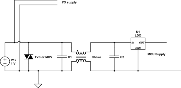
You can eliminate the worry about false triggering. The noise could come from Vcc and not from signal. The easiest is to use a BJT. If noise is a concern, then you might install a differential choke and cap, MOV where you suppy the output Vcc. Or viceversa, you add this filter to the input of MCU power supply and left unfiltered for external I/O signals.
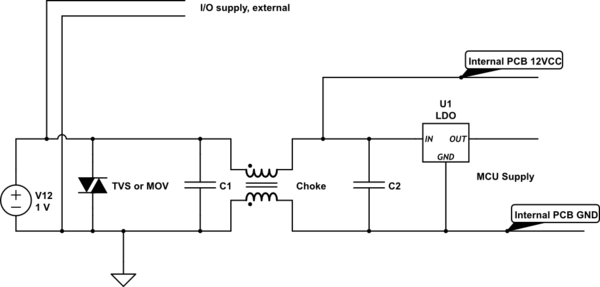
schematic

simulate this circuit – Schematic created using CircuitLab

But most likely you won't have any issues even if the 12V Vcc goes 5m away, since you have also a low pass filter before and after LDO which supplies the MCU.
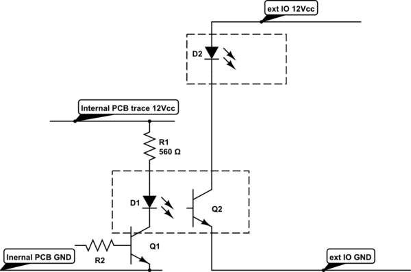
schematic

simulate this circuit

Professional PLC sytem using same power supply for MCU and IO with choke and opto coupled IO signals.

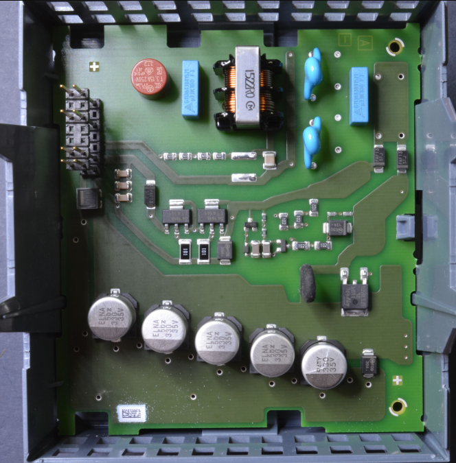
enter image description here

The phototranstor browns out over time, so the CTR ratio falls. You need to supply a consitent current. There are other optos with smaller current also. But your SSR device already has opto isolation, so an open collector BJT can solve this without problem. Open collector output can be used for relativelly long distances, if this is an issue.

EDIT:

You can eliminate the worry about false triggering. The noise could come from Vcc and not from signal. The easiest is to use a BJT. If noise is a concern, then you might install a differential choke and cap, MOV where you suppy the output Vcc. Or viceversa, you add this filter to the input of MCU power supply and left unfiltered for external I/O signals.

schematic

simulate this circuit – Schematic created using CircuitLab

But most likely you won't have any issues even if the 12V Vcc goes 5m away, since you have also a low pass filter before and after LDO which supplies the MCU.

schematic

simulate this circuit

Professional PLC sytem using same power supply for MCU and IO with choke and opto coupled IO signals.
enter image description here

added 798 characters in body
Source Link
Marko Buršič
  • 24.5k
  • 2
  • 21
  • 34

The phototranstor browns out over time, so the CTR ratio falls. You need to supply a consitent current. There are other optos with smaller current also. But your SSR device already has opto isolation, so an open collector BJT can solve this without problem. Open collector output can be used for relativelly long distances, if this is an issue.

EDIT:

You can eliminate the worry about false triggering. The noise could come from Vcc and not from signal. The easiest is to use a BJT. If noise is a concern, then you might install a differential choke and cap, MOV where you suppy the output Vcc. Or viceversa, you add this filter to the input of MCU power supply and left unfiltered for external I/O signals.

schematicschematic

simulate this circuitsimulate this circuit – Schematic created using CircuitLab

But most likely you won't have any issues even if the 12V Vcc goes 5m away, since you have also a low pass filter before and after LDO which supplies the MCU.

schematic

simulate this circuit

The phototranstor browns out over time, so the CTR ratio falls. You need to supply a consitent current. There are other optos with smaller current also. But your SSR device already has opto isolation, so an open collector BJT can solve this without problem. Open collector output can be used for relativelly long distances, if this is an issue.

EDIT:

You can eliminate the worry about false triggering. The noise could come from Vcc and not from signal. The easiest is to use a BJT. If noise is a concern, then you might install a differential choke and cap, MOV where you suppy the output Vcc. Or viceversa, you add this filter to the input of MCU power supply and left unfiltered for external I/O signals.

schematic

simulate this circuit – Schematic created using CircuitLab

But most likely you won't have any issues even if the 12V Vcc goes 5m away, since you have also a low pass filter before and after LDO which supplies the MCU.

schematic

simulate this circuit

added 798 characters in body
Source Link
Marko Buršič
  • 24.5k
  • 2
  • 21
  • 34

The phototranstor browns out over time, so the CTR ratio falls. You need to supply a consitent current. There are other optos with smaller current also. But your SSR device already has opto isolation, so an open collector BJT can solve this without problem. Open collector output can be used for relativelly long distances, if this is an issue.

EDIT:

You can eliminate the worry about false triggering. The noise could come from Vcc and not from signal. The easiest is to use a BJT. If noise is a concern, then you might install a differential choke and cap, MOV where you suppy the output Vcc. Or viceversa, you add this filter to the input of MCU power supply and left unfiltered for external I/O signals.

schematic

simulate this circuit – Schematic created using CircuitLab

But most likely you won't have any issues even if the 12V Vcc goes 5m away, since you have also a low pass filter before and after LDO which supplies the MCU.

The phototranstor browns out over time, so the CTR ratio falls. You need to supply a consitent current. There are other optos with smaller current also. But your SSR device already has opto isolation, so an open collector BJT can solve this without problem. Open collector output can be used for relativelly long distances, if this is an issue.

The phototranstor browns out over time, so the CTR ratio falls. You need to supply a consitent current. There are other optos with smaller current also. But your SSR device already has opto isolation, so an open collector BJT can solve this without problem. Open collector output can be used for relativelly long distances, if this is an issue.

EDIT:

You can eliminate the worry about false triggering. The noise could come from Vcc and not from signal. The easiest is to use a BJT. If noise is a concern, then you might install a differential choke and cap, MOV where you suppy the output Vcc. Or viceversa, you add this filter to the input of MCU power supply and left unfiltered for external I/O signals.

schematic

simulate this circuit – Schematic created using CircuitLab

But most likely you won't have any issues even if the 12V Vcc goes 5m away, since you have also a low pass filter before and after LDO which supplies the MCU.

Source Link
Marko Buršič
  • 24.5k
  • 2
  • 21
  • 34
Loading