Post Reopened by winny, Michel Keijzers, Passerby, Nick Alexeev
edited title
Link
JRE
  • 73.5k
  • 10
  • 112
  • 194

RESOLVED Identifying an unknown code "W62" SOT363 dual inverter

added 508 characters in body; edited title
Source Link

RESOLVED Identifying an unknown code "W62" SOT363 dual inverter

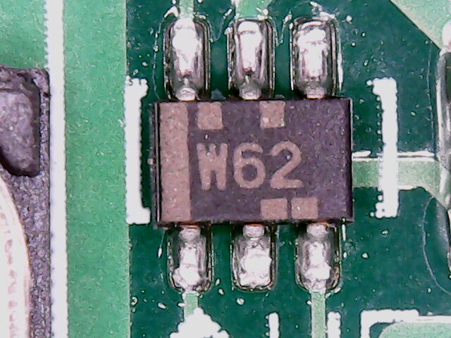
W62 chip

QUESTION: What is this component? RESOLUTION: Equivalent part is SN74LVC2GU04DCKT normally code "CDK" This appears to be specially "Wacom" branded for obscurity. Question below for historical context.

I have a component from a Wacom DTK-2100 digitizer board that I'm struggling to identify. It is presently situated in a fully functional board.

Some context information, Top middle pin is 5V, bottom middle pin is 0V The top right and bottom left pins have no resistance between them, in a functional circuit, the Top left had 2.86V, and the bottom right had 2.2V, the Bottom Left/Top Right had 1.75V.

Any suggestions on what I could try replacing this with in the event that it cannot be identified? Looking up the short code brings be to an SOT323 package, and 3 pins simply won't do.

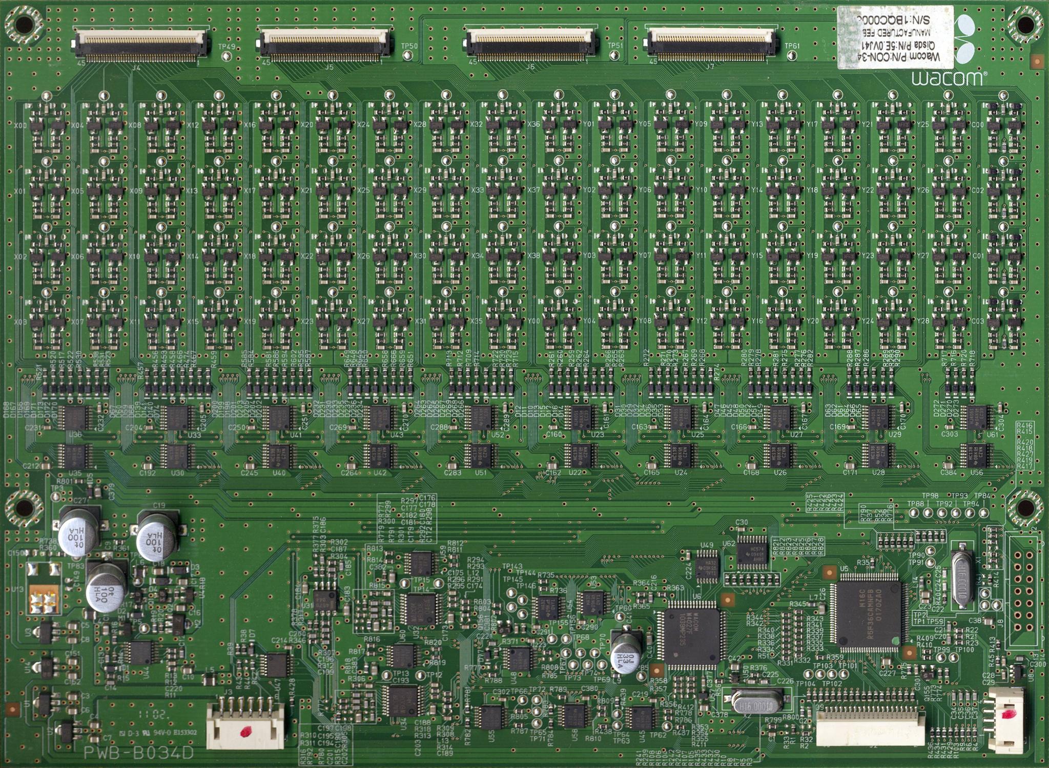
For more context here is a scan of the board from someone else. This component is in the Bottom Right quadrant between the horizontal quartz crystal and the WACOM QFP component. It is marked U50 on the PCB.

Current presumption: I took a look at a same generation model and the component was a "CDK" dual inverter as anticipated by one of the commenters. Link to datasheet: http://www.ti.com/lit/ds/symlink/sn74lvc2gu04.pdf

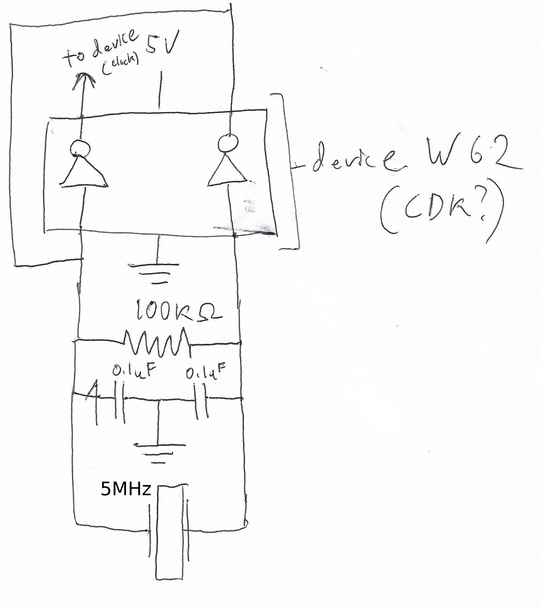
I included a more complete schematic of the circuit now that I'm reasonably sure of what it is and knowledgeable of the neighboring components. It appears Wacom rebranded the device to obscure its function in higher end models.

(Side note, for those attempting digitizer repair on DTK-2100 boards, if there is no -4V line, in the center of the board (should have +5V +4V and -4V rails mid board, and +5, +5 and +3.3 rails along the edge of the board) then most likely this component is the defective culprit as the clock is needed to generate an inverting signal.)

Wacom Board Scan

Circuit Diagram

Identifying an unknown code "W62" SOT363 dual inverter

W62 chip

QUESTION: What is this component?

I have a component from a Wacom DTK-2100 digitizer board that I'm struggling to identify. It is presently situated in a fully functional board.

Some context information, Top middle pin is 5V, bottom middle pin is 0V The top right and bottom left pins have no resistance between them, in a functional circuit, the Top left had 2.86V, and the bottom right had 2.2V, the Bottom Left/Top Right had 1.75V.

Any suggestions on what I could try replacing this with in the event that it cannot be identified? Looking up the short code brings be to an SOT323 package, and 3 pins simply won't do.

For more context here is a scan of the board from someone else. This component is in the Bottom Right quadrant between the horizontal quartz crystal and the WACOM QFP component. It is marked U50 on the PCB.

Current presumption: I took a look at a same generation model and the component was a "CDK" dual inverter as anticipated by one of the commenters. Link to datasheet: http://www.ti.com/lit/ds/symlink/sn74lvc2gu04.pdf

I included a more complete schematic of the circuit now that I'm reasonably sure of what it is and knowledgeable of the neighboring components. It appears Wacom rebranded the device to obscure its function in higher end models.

Wacom Board Scan

Circuit Diagram

RESOLVED Identifying an unknown code "W62" SOT363 dual inverter

W62 chip

QUESTION: What is this component? RESOLUTION: Equivalent part is SN74LVC2GU04DCKT normally code "CDK" This appears to be specially "Wacom" branded for obscurity. Question below for historical context.

I have a component from a Wacom DTK-2100 digitizer board that I'm struggling to identify. It is presently situated in a fully functional board.

Some context information, Top middle pin is 5V, bottom middle pin is 0V The top right and bottom left pins have no resistance between them, in a functional circuit, the Top left had 2.86V, and the bottom right had 2.2V, the Bottom Left/Top Right had 1.75V.

Any suggestions on what I could try replacing this with in the event that it cannot be identified? Looking up the short code brings be to an SOT323 package, and 3 pins simply won't do.

For more context here is a scan of the board from someone else. This component is in the Bottom Right quadrant between the horizontal quartz crystal and the WACOM QFP component. It is marked U50 on the PCB.

Current presumption: I took a look at a same generation model and the component was a "CDK" dual inverter as anticipated by one of the commenters. Link to datasheet: http://www.ti.com/lit/ds/symlink/sn74lvc2gu04.pdf

I included a more complete schematic of the circuit now that I'm reasonably sure of what it is and knowledgeable of the neighboring components. It appears Wacom rebranded the device to obscure its function in higher end models.

(Side note, for those attempting digitizer repair on DTK-2100 boards, if there is no -4V line, in the center of the board (should have +5V +4V and -4V rails mid board, and +5, +5 and +3.3 rails along the edge of the board) then most likely this component is the defective culprit as the clock is needed to generate an inverting signal.)
Wacom Board Scan

Circuit Diagram

deleted 763 characters in body; edited title
Source Link

Identifying an unknown code "W62" SOT363 (transistor?)dual inverter

W62 chip

EDIT 3: QUESTIONQUESTION: What is this component?

I am attempting a repair of an electronic device, but I have limited my question to "What is this device" and included relevant additional information that may be helpful in identifying the component, I am open to any suggestions on how to further identify the component, i.e. isolating it and running specific tests or setting up a circuit to test it if needed.

I have a component from a Wacom DTK-2100 digitizer board that I'm struggling to identify. I believe it may beIt is presently situated in a faulty component as it seems to be outputting the incorrect voltage. I would like to replace it as part of the diagnostic process, but I can't identify it..fully functional board. [end Edit 3]

Some context information, Top middle pin is 5V, bottom middle pin is 0V The top right and bottom left pins have no resistance between them, in a functional circuit, the Top left had 2.86V, and the bottom right had 2.2V, the Bottom Left/Top Right had 1.75V. In a bad circuit, the Top left had 0V, and the bottom right had nearly 0V (millivolts), the Bottom Left/Top Right had 5V.

Any suggestions on what I could try replacing this with in the event that it cannot be identified? Looking up the short code brings be to an SOT323 package, and 3 pins simply won't do.

EDIT: ForFor more context here is a scan of the board from someone else. This component is in the Bottom Right quadrant between the horizontal quartz crystal and the WACOM QFP component. It is marked U50 on the PCB.

EDIT2Current presumption: I looked at the output from the pins on a scope, wayyyy more interesting than with a multimeter. The top Left is putting out I took a distorted sine wave between -2 and 5V (distorting because caps at 5V)look at about 2.8KHz. The Bottom Left (i.e. Top Right) has a sine from -2 to 5V at about 1.6KHz. It is clear that there are 5V and 0V inputs to the top and bottom centers respectively. Botton Right is steady at 2Vsame generation model and seems to determine the centercomponent was a "CDK" dual inverter as anticipated by one of the sine wave, resulting in the wave being basically 2V+4*Sin(x), the W62 seemscommenters. Link to multiplydatasheet: http://www.ti.com/lit/ds/symlink/sn74lvc2gu04.pdf

I included a more complete schematic of the frequency and outputcircuit now that I'm reasonably sure of what it toward the QFP,is and the resistor dampensknowledgeable of the frequencyneighboring components. More informationIt appears Wacom rebranded the device to comeobscure its function in higher end models.

Wacom Board Scan

Circuit Diagram

Identifying an unknown SOT363 (transistor?)

W62 chip

EDIT 3: QUESTION: What is this component?

I am attempting a repair of an electronic device, but I have limited my question to "What is this device" and included relevant additional information that may be helpful in identifying the component, I am open to any suggestions on how to further identify the component, i.e. isolating it and running specific tests or setting up a circuit to test it if needed.

I have a component from a Wacom DTK-2100 digitizer board that I'm struggling to identify. I believe it may be a faulty component as it seems to be outputting the incorrect voltage. I would like to replace it as part of the diagnostic process, but I can't identify it... [end Edit 3]

Some context information, Top middle pin is 5V, bottom middle pin is 0V The top right and bottom left pins have no resistance between them, in a functional circuit, the Top left had 2.86V, and the bottom right had 2.2V, the Bottom Left/Top Right had 1.75V. In a bad circuit, the Top left had 0V, and the bottom right had nearly 0V (millivolts), the Bottom Left/Top Right had 5V.

Any suggestions on what I could try replacing this with in the event that it cannot be identified? Looking up the short code brings be to an SOT323 package, and 3 pins simply won't do.

EDIT: For more context here is a scan of the board from someone else. This component is in the Bottom Right quadrant between the horizontal quartz crystal and the WACOM QFP component. It is marked U50

EDIT2: I looked at the output from the pins on a scope, wayyyy more interesting than with a multimeter. The top Left is putting out a distorted sine wave between -2 and 5V (distorting because caps at 5V) at about 2.8KHz. The Bottom Left (i.e. Top Right) has a sine from -2 to 5V at about 1.6KHz. It is clear that there are 5V and 0V inputs to the top and bottom centers respectively. Botton Right is steady at 2V and seems to determine the center of the sine wave, resulting in the wave being basically 2V+4*Sin(x), the W62 seems to multiply the frequency and output it toward the QFP, and the resistor dampens the frequency. More information to come.

Wacom Board Scan

Identifying an unknown code "W62" SOT363 dual inverter

W62 chip

QUESTION: What is this component?

I have a component from a Wacom DTK-2100 digitizer board that I'm struggling to identify. It is presently situated in a fully functional board.

Some context information, Top middle pin is 5V, bottom middle pin is 0V The top right and bottom left pins have no resistance between them, in a functional circuit, the Top left had 2.86V, and the bottom right had 2.2V, the Bottom Left/Top Right had 1.75V.

Any suggestions on what I could try replacing this with in the event that it cannot be identified? Looking up the short code brings be to an SOT323 package, and 3 pins simply won't do.

For more context here is a scan of the board from someone else. This component is in the Bottom Right quadrant between the horizontal quartz crystal and the WACOM QFP component. It is marked U50 on the PCB.

Current presumption: I took a look at a same generation model and the component was a "CDK" dual inverter as anticipated by one of the commenters. Link to datasheet: http://www.ti.com/lit/ds/symlink/sn74lvc2gu04.pdf

I included a more complete schematic of the circuit now that I'm reasonably sure of what it is and knowledgeable of the neighboring components. It appears Wacom rebranded the device to obscure its function in higher end models.

Wacom Board Scan

Circuit Diagram

Inserted question limited to the tagged categories.
Source Link
Loading
Post Closed as "Not suitable for this site" by Nick Alexeev
added 659 characters in body
Source Link
Loading
Tweeted twitter.com/StackElectronix/status/1049675967705358336
added 280 characters in body
Source Link
Loading
Improved tags (especially adding "identification" tag). Removed polite but unnecessary greeting, per site rules.
Source Link
SamGibson
  • 18.3k
  • 5
  • 41
  • 63
Loading
Source Link
Loading