added 4 characters in body
Source Link
Andy
  • 295
  • 2
  • 9

I have a PIR: [Panasonic NaPiOn AMN34112][1]Panasonic NaPiOn AMN34112 that has a digital output. When it detects motion it outputs 4V and 100 uA max. I want to connect this output to a LED using one or more transistor amplifier stages. Before I do that I want to model what happens in the circuit simulator Every Circuit. How do I model a digital output? I want to make sure I am not sourcing more than 100 uA from the PIR. I was thinking modelling the PIR as a 4V battery. Is this wrong?

EDIT: after reading your answers I understand that this is very wrong. Instead I will try this:

[![enter image description here][2]][2]enter image description here
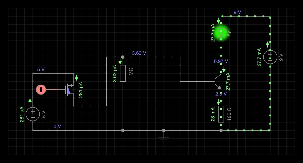
I used the default mosfet in the circuit simulator. In this circuit it has a voltage drop of V_SD = 1.4 V whereas I_DS is 281 uA => R_DS(on) = 1.4/2.8 E-4 = 5K Ohm which is the same as you mentioned.
[1]: https://www.elfadistrelec.no/Web/Downloads/_t/ds/PaPIR_NaPiOn_eng_tds.pdf [2]: https://i.sstatic.net/Xf2UE.png

I have a PIR: [Panasonic NaPiOn AMN34112][1] that has a digital output. When it detects motion it outputs 4V and 100 uA max. I want to connect this output to a LED using one or more transistor amplifier stages. Before I do that I want to model what happens in the circuit simulator Every Circuit. How do I model a digital output? I want to make sure I am not sourcing more than 100 uA from the PIR. I was thinking modelling the PIR as a 4V battery. Is this wrong?

EDIT: after reading your answers I understand that this is very wrong. Instead I will try this:

[![enter image description here][2]][2]

I used the default mosfet in the circuit simulator. In this circuit it has a voltage drop of V_SD = 1.4 V whereas I_DS is 281 uA => R_DS(on) = 1.4/2.8 E-4 = 5K Ohm which is the same as you mentioned.
[1]: https://www.elfadistrelec.no/Web/Downloads/_t/ds/PaPIR_NaPiOn_eng_tds.pdf [2]: https://i.sstatic.net/Xf2UE.png

I have a PIR: Panasonic NaPiOn AMN34112 that has a digital output. When it detects motion it outputs 4V and 100 uA max. I want to connect this output to a LED using one or more transistor amplifier stages. Before I do that I want to model what happens in the circuit simulator Every Circuit. How do I model a digital output? I want to make sure I am not sourcing more than 100 uA from the PIR. I was thinking modelling the PIR as a 4V battery. Is this wrong?

EDIT: after reading your answers I understand that this is very wrong. Instead I will try this:

enter image description here

I used the default mosfet in the circuit simulator. In this circuit it has a voltage drop of V_SD = 1.4 V whereas I_DS is 281 uA => R_DS(on) = 1.4/2.8 E-4 = 5K Ohm which is the same as you mentioned.

added 389 characters in body
Source Link
Andy
  • 295
  • 2
  • 9

I have a PIR: Panasonic NaPiOn AMN34112[Panasonic NaPiOn AMN34112][1] that has a digital output. When it detects motion it outputs 4V and 100 uA max. I want to connect this output to a LED using one or more transistor amplifier stages. Before I do that I want to model what happens in the circuit simulator Every Circuit. How do I model a digital output? I want to make sure I am not sourcing more than 100 uA from the PIR. I was thinking modelling the PIR as a 4V battery. Is this wrong?

EDIT: after reading your answers I understand that this is very wrong. Instead I will try this:

[![enter image description here][2]][2]

I used the default mosfet in the circuit simulator. In this circuit it has a voltage drop of V_SD = 1.4 V whereas I_DS is 281 uA => R_DS(on) = 1.4/2.8 E-4 = 5K Ohm which is the same as you mentioned.
[1]: https://www.elfadistrelec.no/Web/Downloads/_t/ds/PaPIR_NaPiOn_eng_tds.pdf [2]: https://i.sstatic.net/Xf2UE.png

I have a PIR: Panasonic NaPiOn AMN34112 that has a digital output. When it detects motion it outputs 4V and 100 uA max. I want to connect this output to a LED using one or more transistor amplifier stages. Before I do that I want to model what happens in the circuit simulator Every Circuit. How do I model a digital output? I want to make sure I am not sourcing more than 100 uA from the PIR. I was thinking modelling the PIR as a 4V battery. Is this wrong?

I have a PIR: [Panasonic NaPiOn AMN34112][1] that has a digital output. When it detects motion it outputs 4V and 100 uA max. I want to connect this output to a LED using one or more transistor amplifier stages. Before I do that I want to model what happens in the circuit simulator Every Circuit. How do I model a digital output? I want to make sure I am not sourcing more than 100 uA from the PIR. I was thinking modelling the PIR as a 4V battery. Is this wrong?

EDIT: after reading your answers I understand that this is very wrong. Instead I will try this:

[![enter image description here][2]][2]

I used the default mosfet in the circuit simulator. In this circuit it has a voltage drop of V_SD = 1.4 V whereas I_DS is 281 uA => R_DS(on) = 1.4/2.8 E-4 = 5K Ohm which is the same as you mentioned.
[1]: https://www.elfadistrelec.no/Web/Downloads/_t/ds/PaPIR_NaPiOn_eng_tds.pdf [2]: https://i.sstatic.net/Xf2UE.png

added 4 characters in body
Source Link
Andy
  • 295
  • 2
  • 9

I have a PIR: Panasonic NaPiOn AMN34112 that has a digital output. When it detects motion it outputs 4V and 100 uA max. I want to connect this output to a LED using one or more transistor amplifier stages. Before I do that I want to model what happens in the circuit simulator Every Circuit. How do I model a digital output? I want to make sure I am not sourcing more than 100 uA from the PIR. I was thinking modelling the PIR as a 4V battery. Is this wrong?

I have a PIR that has a digital output. When it detects motion it outputs 4V and 100 uA. I want to connect this output to a LED using one or more transistor amplifier stages. Before I do that I want to model what happens in the circuit simulator Every Circuit. How do I model a digital output? I want to make sure I am not sourcing more than 100 uA from the PIR. I was thinking modelling the PIR as a 4V battery. Is this wrong?

I have a PIR: Panasonic NaPiOn AMN34112 that has a digital output. When it detects motion it outputs 4V and 100 uA max. I want to connect this output to a LED using one or more transistor amplifier stages. Before I do that I want to model what happens in the circuit simulator Every Circuit. How do I model a digital output? I want to make sure I am not sourcing more than 100 uA from the PIR. I was thinking modelling the PIR as a 4V battery. Is this wrong?

Source Link
Andy
  • 295
  • 2
  • 9
Loading