Bumped by Community user
Added values and clarified referencs from comments.
Source Link
Warren Hill
  • 4.9k
  • 22
  • 33

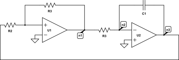
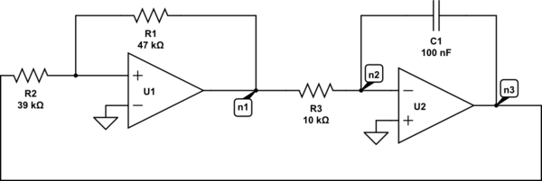
I have the following circuit:
schematicschematic

simulate this circuitsimulate this circuit – Schematic created using CircuitLab

I need to determine period of oscillations for the given circuit and to sketch waveforms of the voltages at nodes n1, n2 and n3.

Values of the resistances and capacitance are known and OPamps are considered to be ideal.

$$R_1=47k\Omega\\ R_2=39k\Omega \\ R_3=10k\Omega \\ C=100nF$$

Basically, what I can see here, is that this circuit consists of an inverting amplifier in series with an integrator (correct me if I am wrong), but I really cannot see the way to sketch the waveforms required since I cannot see what is actually going on here.

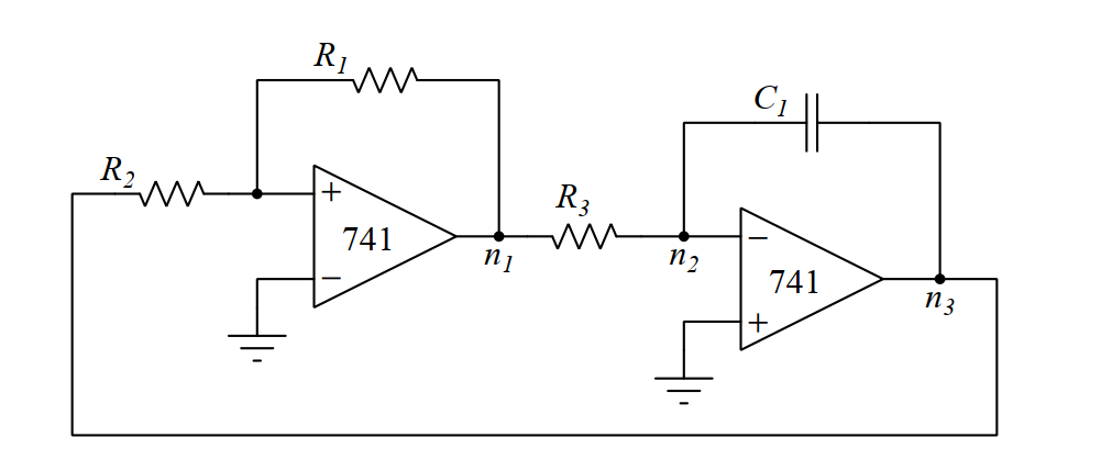
I have the following circuit:

schematic

simulate this circuit – Schematic created using CircuitLab

I need to determine period of oscillations for the given circuit and to sketch waveforms of the voltages at nodes n1, n2 and n3.

Values of the resistances and capacitance are known and OPamps are considered to be ideal.

$$R_1=47k\Omega\\ R_2=39k\Omega \\ R_3=10k\Omega \\ C=100nF$$

Basically, what I can see here, is that this circuit consists of an inverting amplifier in series with an integrator (correct me if I am wrong), but I really cannot see the way to sketch the waveforms required since I cannot see what is actually going on here.

deleted 15 characters in body
Source Link
JRE
  • 73.6k
  • 10
  • 112
  • 195

I have the following circuit:

schematic

simulate this circuit – Schematic created using CircuitLab

I need to determine period of oscillations for the given circuit and to sketch waveforms of athe voltages at nodes n1, n2 and n3.

Values of the resistances and capacitance are known and OPamps are considered to be ideal.

$$R_1=47k\Omega\\ R_2=39k\Omega \\ R_3=10k\Omega \\ C=100nF$$

Basically, what iI can see here, is that this circuit consists of an inverting amplifier in series with an integrator (correct me if iI am wrong), but iI really cannot see the way to sketch the waveforms required since iI cannot see what is actually going on here. Any help appreciated!

I have the following circuit:

schematic

simulate this circuit – Schematic created using CircuitLab

I need to determine period of oscillations for the given circuit and to sketch waveforms of a voltages at nodes n1, n2 and n3.

Values of the resistances and capacitance are known and OPamps are considered to be ideal.

$$R_1=47k\Omega\\ R_2=39k\Omega \\ R_3=10k\Omega \\ C=100nF$$

Basically, what i can see here, is that this circuit consists of inverting amplifier in series with integrator (correct me if i am wrong), but i really cannot see the way to sketch the waveforms required since i cannot see what is actually going on here. Any help appreciated!

I have the following circuit:

schematic

simulate this circuit – Schematic created using CircuitLab

I need to determine period of oscillations for the given circuit and to sketch waveforms of the voltages at nodes n1, n2 and n3.

Values of the resistances and capacitance are known and OPamps are considered to be ideal.

$$R_1=47k\Omega\\ R_2=39k\Omega \\ R_3=10k\Omega \\ C=100nF$$

Basically, what I can see here, is that this circuit consists of an inverting amplifier in series with an integrator (correct me if I am wrong), but I really cannot see the way to sketch the waveforms required since I cannot see what is actually going on here.

added 277 characters in body
Source Link
Marcus Müller
  • 100k
  • 5
  • 141
  • 262

I have the following circuit:


enter image description hereschematic

simulate this circuit – Schematic created using CircuitLab

I need to determine period of oscillations for the given circuit and to sketch waveforms of a voltages at nodes n1, n2 and n3.

Values of the resistances and capacitance are known and OPamps are considered to be ideal.

$$R_1=47k\Omega\\ R_2=39k\Omega \\ R_3=10k\Omega \\ C=100nF$$

Basically, what i can see here, is that this circuit consists of inverting amplifier in series with integrator (correct me if i am wrong), but i really cannot see the way to sketch the waveforms required since i cannot see what is actually going on here. Any help appreciated!

I have the following circuit:


enter image description here

I need to determine period of oscillations for the given circuit and to sketch waveforms of a voltages at nodes n1, n2 and n3.

Values of the resistances and capacitance are known and OPamps are considered to be ideal.

$$R_1=47k\Omega\\ R_2=39k\Omega \\ R_3=10k\Omega \\ C=100nF$$

Basically, what i can see here, is that this circuit consists of inverting amplifier in series with integrator (correct me if i am wrong), but i really cannot see the way to sketch the waveforms required since i cannot see what is actually going on here. Any help appreciated!

I have the following circuit:


schematic

simulate this circuit – Schematic created using CircuitLab

I need to determine period of oscillations for the given circuit and to sketch waveforms of a voltages at nodes n1, n2 and n3.

Values of the resistances and capacitance are known and OPamps are considered to be ideal.

$$R_1=47k\Omega\\ R_2=39k\Omega \\ R_3=10k\Omega \\ C=100nF$$

Basically, what i can see here, is that this circuit consists of inverting amplifier in series with integrator (correct me if i am wrong), but i really cannot see the way to sketch the waveforms required since i cannot see what is actually going on here. Any help appreciated!

Source Link
cdummie
  • 237
  • 3
  • 12
Loading