how the above calculations can be translated to bits per second, because everyone filters the optocouplers according to their Data rate (bps).
A 10 us pulse would be equivalent to a 100 kbps digital data rate.
NRZ...01010 is 50 kHz or 20us
Since Tr=0.35/f-3dB = rise time 10~90% using 10101 = f/2 **at bit rate = f **
for 10101 pattern cycle of 20us at 100kbps NRZ max Tr= 7us but lower is better for InterSymbol Interference ISI ( from group delay) so you get lower BER with more phase margin from reduced ISI. (eye pattern)
Another question is about the input current of the optocoupler. My microcontroller can only provide around 4-6 mA through its PWM ports.
No, that is only true for logic noise margin. Here the Logic margin is your OptoIsolator output. The port is spec'd as VOL Low-level output voltage, driver enabled, pullup or pulldown disabled IOL = 6 mA 0.45 V
This means Zol= 0.45/6mA = 75 Ohm RdsOn , same for VOH. REF p90
N.B> Note that Cortex driver specs are worst case (+50%) and CMOS RdsOn at rate supply is usually 50 Ω +/-50% . ALV logic is 1/2 of Ω this.
Short circuit power in driver is then 145 mW so you can include this Rs with your IR current limit calculations for series R. and use near IR max If current e.g. 12mA
I agree with @Photon, You want to look for the "current transfer ratio" or CTR and rise time. Worst case CTR can be 25% which is like Beta (hFE) in a transistor.
The only tradeoff is the speed or TPLH with a Darlington , which makes this design marginal.
So, for example, this datasheet is from the 6N138M optocoupler. One can see under the "features" section: "Low Current-0.5mA".
A single transistor when saturated has about 10~20% hFE same with a Darlington
which has hFE² or a saturated gain of 10²=100
The datasheet best case propagation delay time is TPLH= 7us max 0~70'C and 1.3us typ at 25'C with the following conditions;
RL=270 Ω If=12mA with 270 Ω to 5V - (Vol(sat)=1.2V est.) yield Ic= 3.8V/270=14mA .
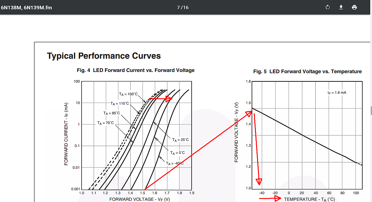
To get If=12mA from 3.3V 75 Ω Beagleboard CMOS driver into is unreliable as temp changes VF which increases IR temp and exceeds MAX so a 5V current limit is better. Fig 4 in datasheet shows Vf ranges from 1.5V to 1.8V so ΔV=Vdd-Vf=1.8 to 1.5V so using 1.8V/12mA = 46Ω which is less than the Driver Rs 75 Ohms max(25 min) which also has a 25% tolerance. Using 1.5V/12mA=125Ω , Since driver is 33 to 75 Ohms 126-70=56 Ohms
But under absolute maximum ratings, it says that If can reach 20mA.
There is also Fig 5 Vf vs Ta which says if you run at 1.5V the self-heating requires your ambient to be -40'C for cooling.
From what I understand, my optocoupler should be fast enough, so that it can transmit the narrowest pulse (1% duty cycle), which has a duration of 1%*(1/1000) = 10μseconds. Consequently, I need to have: tr+tf < 10μsec,
Yes, the rise time may meet the 7uS max requirement and I expect rise time to be less than propagation delay which is the only spec given. So rise time depends on bandwidth and prop delay. If you have 5V you must use this with driver Sch. Diode protection to regulate Vf so temperature of IR diode has less effect on the If stability.
