deleted 1 character in body
Source Link
D.A.S.
  • 148k
  • 3
  • 56
  • 190

The problem with the original idea with 1 cell is the battery operates down near 3V or so and the LED operates from 3.2 to 2.9V depending on datasheet specs. This means using Vbe to sense current across 1 Ohm is too much voltage drop.

100 mOhm is more appropriate.

This will be a good tradeoff from the option to buy a buckboost LED CC driver to the efficiency of a simple FET CC regulator. 600mA~700mA Constant Current Sink low voltage drop
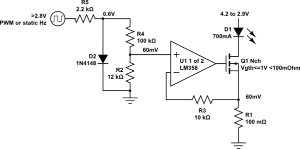
schematic

simulate this circuit – Schematic created using CircuitLab

Adjust R12R2 voltage to regulate current across 100mOhm.

You can also replace diode with Yellow LED 2mA at 2V with adequate brightness using R5 = ~680 ohm and scale down to same Vin-.

If you need more mAh then shunt matched cells together when at the same voltage.

I intentionally reduced your 3W LED to 2W but if you are confident your heatsink is adequate not to burn to touch and can accept a short battery discharge time, you can go for 1A.

The problem with the original idea with 1 cell is the battery operates down near 3V or so and the LED operates from 3.2 to 2.9V depending on datasheet specs. This means using Vbe to sense current across 1 Ohm is too much voltage drop.

100 mOhm is more appropriate.

This will be a good tradeoff from the option to buy a buckboost LED CC driver to the efficiency of a simple FET CC regulator. 600mA~700mA Constant Current Sink low voltage drop

schematic

simulate this circuit – Schematic created using CircuitLab

Adjust R12 voltage to regulate current across 100mOhm.

You can also replace diode with Yellow LED 2mA at 2V with adequate brightness using R5 = ~680 ohm and scale down to same Vin-.

The problem with the original idea with 1 cell is the battery operates down near 3V or so and the LED operates from 3.2 to 2.9V depending on datasheet specs. This means using Vbe to sense current across 1 Ohm is too much voltage drop.

100 mOhm is more appropriate.

This will be a good tradeoff from the option to buy a buckboost LED CC driver to the efficiency of a simple FET CC regulator. 600mA~700mA Constant Current Sink low voltage drop

schematic

simulate this circuit – Schematic created using CircuitLab

Adjust R2 voltage to regulate current across 100mOhm.

You can also replace diode with Yellow LED 2mA at 2V with adequate brightness using R5 = ~680 ohm and scale down to same Vin-.

If you need more mAh then shunt matched cells together when at the same voltage.

I intentionally reduced your 3W LED to 2W but if you are confident your heatsink is adequate not to burn to touch and can accept a short battery discharge time, you can go for 1A.

added 45 characters in body
Source Link
D.A.S.
  • 148k
  • 3
  • 56
  • 190

TeThe problem with the original idea with 1 cell is the battery operates down near 3V or so and the LED operates from 3.2 to 2.9V depending on datasheet specs. This means using Vbe to sense current across 1 Ohm is too much voltage drop.

100 mOhm is more appropriate.

This will be a good tradeoff from the option to buy a buckboost LED CC driver to the efficiency of a simple FET CC regulator. 600mA~700mA Constant Current Sink low voltage drop

schematic

simulate this circuit – Schematic created using CircuitLab

Adjust R12 voltage to regulate current across 100mOhm.

You can also replace diode with Yellow LED 2mA at 2V with adequate brightness using R5 = ~680 ohm and scale down to same Vin-.

Te problem with the original idea with 1 cell is the battery operates down near 3V or so and the LED operates from 3.2 to 2.9V depending on datasheet specs. This means using Vbe to sense current across 1 Ohm is too much voltage drop.

100 mOhm is more appropriate.

This will be a good tradeoff from the option to buy a buckboost LED CC driver to the efficiency of a simple FET CC regulator. 600mA~700mA Constant Current Sink low voltage drop

schematic

simulate this circuit – Schematic created using CircuitLab

Adjust R12 voltage to regulate current across 100mOhm.

You can also replace diode with Yellow LED 2mA at 2V and scale down to same Vin-.

The problem with the original idea with 1 cell is the battery operates down near 3V or so and the LED operates from 3.2 to 2.9V depending on datasheet specs. This means using Vbe to sense current across 1 Ohm is too much voltage drop.

100 mOhm is more appropriate.

This will be a good tradeoff from the option to buy a buckboost LED CC driver to the efficiency of a simple FET CC regulator. 600mA~700mA Constant Current Sink low voltage drop

schematic

simulate this circuit – Schematic created using CircuitLab

Adjust R12 voltage to regulate current across 100mOhm.

You can also replace diode with Yellow LED 2mA at 2V with adequate brightness using R5 = ~680 ohm and scale down to same Vin-.

Source Link
D.A.S.
  • 148k
  • 3
  • 56
  • 190

Te problem with the original idea with 1 cell is the battery operates down near 3V or so and the LED operates from 3.2 to 2.9V depending on datasheet specs. This means using Vbe to sense current across 1 Ohm is too much voltage drop.

100 mOhm is more appropriate.

This will be a good tradeoff from the option to buy a buckboost LED CC driver to the efficiency of a simple FET CC regulator. 600mA~700mA Constant Current Sink low voltage drop

schematic

simulate this circuit – Schematic created using CircuitLab

Adjust R12 voltage to regulate current across 100mOhm.

You can also replace diode with Yellow LED 2mA at 2V and scale down to same Vin-.