added 3 characters in body
Source Link

I am having issues with this previously designed circuit from a former workerco-worker. What we want it to do is turn on the LED when IN1 of TPS2121 (Power mux) is chosen as the output. According to the datasheet ST is pulled high when the output is Hi-Z or IN1 and pulled low when IN2 is powering the output. The LED is part of the switch PVA6LRE21141 I can't find the forward voltage it requires but with the current design, voltage across the diode is only 2.6V.

I do not understand his BJT circuit, the LED is not very bright at the status pin I only see 3.1V. I am trying to get it to turn brighter. Can someone explain the purpose of R14 and the way it is connected. Only R13 seems to affect the brightness, except I cannot decrease it any lower than 6K or I would violate the specifications of the TPS2121 ST pin. The ST pin requires a pull up from 6K-20K.

I think he used a BJT with C8 and R15 to create a ramp up effect for the LED. I do not think the ramp up is that necessary. Is there anyway I can change this design without having to change the PCB or as little as possible so that the LED can turn on brighter? I am considering changing Q1 to a mosfet with common footprint and removing C8. Thanks in advance for your help!

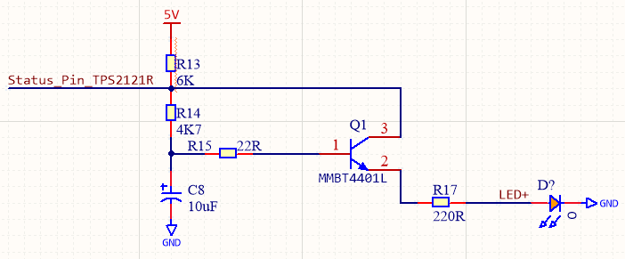
BJT design

I am having issues with this previously designed circuit from a former worker. What we want it to do is turn on the LED when IN1 of TPS2121 (Power mux) is chosen as the output. According to the datasheet ST is pulled high when the output is Hi-Z or IN1 and pulled low when IN2 is powering the output. The LED is part of the switch PVA6LRE21141 I can't find the forward voltage it requires but with the current design, voltage across the diode is only 2.6V.

I do not understand his BJT circuit, the LED is not very bright at the status pin I only see 3.1V. I am trying to get it to turn brighter. Can someone explain the purpose of R14 and the way it is connected. Only R13 seems to affect the brightness, except I cannot decrease it any lower than 6K or I would violate the specifications of the TPS2121 ST pin. The ST pin requires a pull up from 6K-20K.

I think he used a BJT with C8 and R15 to create a ramp up effect for the LED. I do not think the ramp up is that necessary. Is there anyway I can change this design without having to change the PCB or as little as possible so that the LED can turn on brighter? I am considering changing Q1 to a mosfet with common footprint and removing C8. Thanks in advance for your help!

BJT design

I am having issues with this previously designed circuit from a former co-worker. What we want it to do is turn on the LED when IN1 of TPS2121 (Power mux) is chosen as the output. According to the datasheet ST is pulled high when the output is Hi-Z or IN1 and pulled low when IN2 is powering the output. The LED is part of the switch PVA6LRE21141 I can't find the forward voltage it requires but with the current design, voltage across the diode is only 2.6V.

I do not understand his BJT circuit, the LED is not very bright at the status pin I only see 3.1V. I am trying to get it to turn brighter. Can someone explain the purpose of R14 and the way it is connected. Only R13 seems to affect the brightness, except I cannot decrease it any lower than 6K or I would violate the specifications of the TPS2121 ST pin. The ST pin requires a pull up from 6K-20K.

I think he used a BJT with C8 and R15 to create a ramp up effect for the LED. I do not think the ramp up is that necessary. Is there anyway I can change this design without having to change the PCB or as little as possible so that the LED can turn on brighter? I am considering changing Q1 to a mosfet with common footprint and removing C8. Thanks in advance for your help!

BJT design

Source Link

How to adjust this BJT design to increase brightness of LED without changing PCB?

I am having issues with this previously designed circuit from a former worker. What we want it to do is turn on the LED when IN1 of TPS2121 (Power mux) is chosen as the output. According to the datasheet ST is pulled high when the output is Hi-Z or IN1 and pulled low when IN2 is powering the output. The LED is part of the switch PVA6LRE21141 I can't find the forward voltage it requires but with the current design, voltage across the diode is only 2.6V.

I do not understand his BJT circuit, the LED is not very bright at the status pin I only see 3.1V. I am trying to get it to turn brighter. Can someone explain the purpose of R14 and the way it is connected. Only R13 seems to affect the brightness, except I cannot decrease it any lower than 6K or I would violate the specifications of the TPS2121 ST pin. The ST pin requires a pull up from 6K-20K.

I think he used a BJT with C8 and R15 to create a ramp up effect for the LED. I do not think the ramp up is that necessary. Is there anyway I can change this design without having to change the PCB or as little as possible so that the LED can turn on brighter? I am considering changing Q1 to a mosfet with common footprint and removing C8. Thanks in advance for your help!

BJT design