Bumped by Community user
added 18 characters in body; edited title
Source Link
JRE
  • 73.6k
  • 10
  • 112
  • 195

Capacitor in parallellparallel with relaycoilrelay coil backfires on contacts

IveI've got a smoothingcapacitorsmoothing capacitor(2,2uF) C1 in parallellparallel with relaycoilsrelay coils inside a fullwave diodebrigdediode bridge.

When the circuit is closed troughthrough contacts in pre-relay RLY1 it first gives me, almost everytime because of capacitive reactance in circuit  (Ce of C1 and C2), an Arc1arc over the contacts of the pre-relay, when circuit is closed. But if I place a resistor R1 infrontin front of capacitor C1 for limitingto limit the inrush charge current of the smoothingcapacitorsmoothing capacitor it will in very short backfiresbackfire into the resistors R2 & R3 and destroy them. Leading to none zenervoltageno zener voltage.

Placing a diode in parallell with resistor R1 for bypassing of the charge current in one direction will end up in almost the same way with destroyed resistors R2 & R3, but not until after almost 1000 tries.

Why is this happening and how tocan I stabilize the circuit so the smoothingcapacitor isntsmoothing capacitor isn't giving me an arc in either the pre-relay contacts neither backfire into the resistors.? Because of C2 theresthere's around 45-50VDC left inside diodebrigdethe diode bridge. Any ideas?
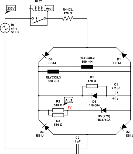
schematic

simulate this circuit – Schematic created using CircuitLab

Edit schematic: Added R4, an ICL NTC for inrush current limit.

Second edit:

Below answer helped me on the way, thanks! As you pointed out @SpheroPefhany, D6 should be the other way around pointing cathode away(changed in schematics) from smoothing capacitor C1. I've tested some new things to increase the effect over R4(changed to 220Ω) with a TRIAC bypassing(edited as Figure 1) and also found another idea regarding the use of a TRIAC(Figure2 in orange dashed box) or DIAC(in blue dashed box) in serieseries with the zener D5, without the R4 in the circuit. However, to ensure the heat won't destroy the circuit, it needs to switch fast enough to decrease the heat during opening. Is this a working approchapproach or have I missed something?

See updated schematics.
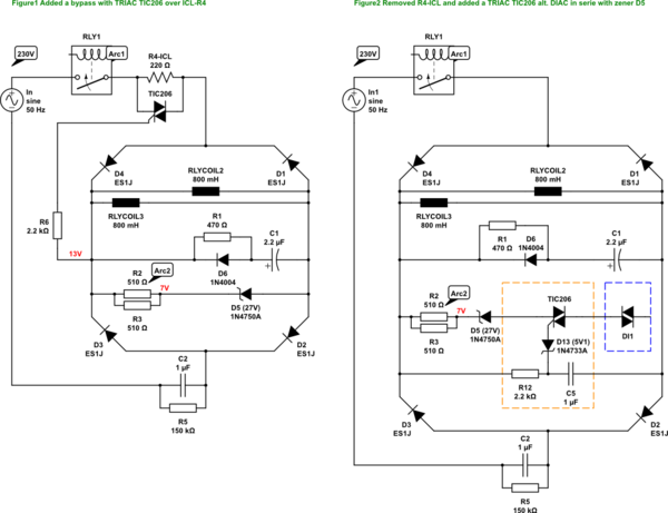
schematic

simulate this circuit

Capacitor in parallell with relaycoil backfires on contacts

Ive got a smoothingcapacitor(2,2uF) C1 in parallell with relaycoils inside a fullwave diodebrigde.

When circuit is closed trough contacts in pre-relay RLY1 it first gives me, almost everytime because of capacitive reactance in circuit(Ce of C1 and C2), an Arc1 over the contacts of the pre-relay, when circuit is closed. But if I place a resistor R1 infront of capacitor C1 for limiting the inrush charge current of the smoothingcapacitor it will in very short backfires into the resistors R2 & R3 and destroy them. Leading to none zenervoltage.

Placing a diode in parallell with resistor R1 for bypassing of the charge current in one direction will end up in almost the same way with destroyed resistors R2 & R3, but not until after almost 1000 tries.

Why is this happening and how to stabilize the circuit so the smoothingcapacitor isnt giving me an arc in either the pre-relay contacts neither backfire into the resistors. Because of C2 theres around 45-50VDC left inside diodebrigde. Any ideas?

schematic

simulate this circuit – Schematic created using CircuitLab

Edit schematic: Added R4, an ICL NTC for inrush current limit

Second edit:

Below answer helped me on the way, thanks! As you pointed out @SpheroPefhany, D6 should be the other way around pointing cathode away(changed in schematics) from smoothing capacitor C1. I've tested some new things to increase the effect over R4(changed to 220Ω) with a TRIAC bypassing(edited as Figure 1) and also found another idea regarding the use of a TRIAC(Figure2 in orange dashed box) or DIAC(in blue dashed box) in serie with the zener D5, without the R4 in the circuit. However, to ensure the heat won't destroy the circuit, it needs to switch fast enough to decrease the heat during opening. Is this a working approch or have I missed something?

See updated schematics.

schematic

simulate this circuit

Capacitor in parallel with relay coil backfires on contacts

I've got a smoothing capacitor(2,2uF) C1 in parallel with relay coils inside a fullwave diode bridge.

When the circuit is closed through contacts in pre-relay RLY1 it first gives me, almost everytime because of capacitive reactance in circuit  (Ce of C1 and C2), an arc over the contacts of the pre-relay, when circuit is closed. But if I place a resistor R1 in front of capacitor C1 to limit the inrush charge current of the smoothing capacitor it will in very short backfire into the resistors R2 & R3 and destroy them. Leading to no zener voltage.

Placing a diode in parallell with resistor R1 for bypassing of the charge current in one direction will end up in almost the same way with destroyed resistors R2 & R3, but not until after almost 1000 tries.

Why is this happening and how can I stabilize the circuit so the smoothing capacitor isn't giving me an arc in either the pre-relay contacts neither backfire into the resistors? Because of C2 there's around 45-50VDC left inside the diode bridge. Any ideas?

schematic

simulate this circuit – Schematic created using CircuitLab

Edit schematic: Added R4, an ICL NTC for inrush current limit.

Second edit:

Below answer helped me on the way, thanks! As you pointed out @SpheroPefhany, D6 should be the other way around pointing cathode away(changed in schematics) from smoothing capacitor C1. I've tested some new things to increase the effect over R4(changed to 220Ω) with a TRIAC bypassing(edited as Figure 1) and also found another idea regarding the use of a TRIAC(Figure2 in orange dashed box) or DIAC(in blue dashed box) in series with the zener D5, without the R4 in the circuit. However, to ensure the heat won't destroy the circuit, it needs to switch fast enough to decrease the heat during opening. Is this a working approach or have I missed something?

See updated schematics.
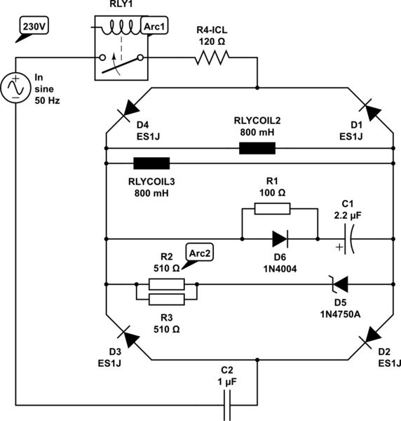
schematic

simulate this circuit

added 969 characters in body; edited tags
Source Link
deel
  • 21
  • 3

Ive got a smoothingcapacitor(2,2uF) C1 in parallell with relaycoils inside a fullwave diodebrigde.

When circuit is closed trough contacts in pre-relay RLY1 it first gives me, almost everytime because of capacitive reactance in circuit(Ce of C1 and C2), an Arc1 over the contacts of the pre-relay, when circuit is closed. But if I place a resistor R1 infront of capacitor C1 for limiting the inrush charge current of the smoothingcapacitor it will in very short backfires into the resistors R2 & R3 and destroy them. Leading to none zenervoltage.

Placing a diode in parallell with resistor R1 for bypassing of the charge current in one direction will end up in almost the same way with destroyed resistors R2 & R3, but not until after almost 1000 tries.

Why is this happening and how to stabilize the circuit so the smoothingcapacitor isnt giving me an arc in either the pre-relay contacts neither backfire into the resistors. Because of C2 theres around 45-50VDC left inside diodebrigde. Any ideas?

schematicschematic

simulate this circuitsimulate this circuit – Schematic created using CircuitLab

Edit schematic: Added R4, an ICL NTC for inrush current limit

Second edit:

Below answer helped me on the way, thanks! As you pointed out @SpheroPefhany, D6 should be the other way around pointing cathode away(changed in schematics) from smoothing capacitor C1. I've tested some new things to increase the effect over R4(changed to 220Ω) with a TRIAC bypassing(edited as Figure 1) and also found another idea regarding the use of a TRIAC(Figure2 in orange dashed box) or DIAC(in blue dashed box) in serie with the zener D5, without the R4 in the circuit. However, to ensure the heat won't destroy the circuit, it needs to switch fast enough to decrease the heat during opening. Is this a working approch or have I missed something?

See updated schematics.

schematic

simulate this circuit

Ive got a smoothingcapacitor(2,2uF) C1 in parallell with relaycoils inside a fullwave diodebrigde.

When circuit is closed trough contacts in pre-relay RLY1 it first gives me, almost everytime because of capacitive reactance in circuit(Ce of C1 and C2), an Arc1 over the contacts of the pre-relay, when circuit is closed. But if I place a resistor R1 infront of capacitor C1 for limiting the inrush charge current of the smoothingcapacitor it will in very short backfires into the resistors R2 & R3 and destroy them. Leading to none zenervoltage.

Placing a diode in parallell with resistor R1 for bypassing of the charge current in one direction will end up in almost the same way with destroyed resistors R2 & R3, but not until after almost 1000 tries.

Why is this happening and how to stabilize the circuit so the smoothingcapacitor isnt giving me an arc in either the pre-relay contacts neither backfire into the resistors. Because of C2 theres around 45-50VDC left inside diodebrigde. Any ideas?

schematic

simulate this circuit – Schematic created using CircuitLab

Edit schematic: Added R4, an ICL NTC for inrush current limit

Second edit:

Below answer helped me on the way, thanks! As you pointed out @SpheroPefhany, D6 should be the other way around pointing cathode away(changed in schematics) from smoothing capacitor C1. I've tested some new things to increase the effect over R4 with a TRIAC bypassing(edited as Figure 1) and also found another idea regarding the use of a TRIAC(Figure2 in orange dashed box) or DIAC(in blue dashed box) in serie with the zener D5. However, to ensure the heat won't destroy the circuit, it needs to switch fast enough to decrease the heat during opening. Is this a working approch or have I missed something?

See updated schematics.

Ive got a smoothingcapacitor(2,2uF) C1 in parallell with relaycoils inside a fullwave diodebrigde.

When circuit is closed trough contacts in pre-relay RLY1 it first gives me, almost everytime because of capacitive reactance in circuit(Ce of C1 and C2), an Arc1 over the contacts of the pre-relay, when circuit is closed. But if I place a resistor R1 infront of capacitor C1 for limiting the inrush charge current of the smoothingcapacitor it will in very short backfires into the resistors R2 & R3 and destroy them. Leading to none zenervoltage.

Placing a diode in parallell with resistor R1 for bypassing of the charge current in one direction will end up in almost the same way with destroyed resistors R2 & R3, but not until after almost 1000 tries.

Why is this happening and how to stabilize the circuit so the smoothingcapacitor isnt giving me an arc in either the pre-relay contacts neither backfire into the resistors. Because of C2 theres around 45-50VDC left inside diodebrigde. Any ideas?

schematic

simulate this circuit – Schematic created using CircuitLab

Edit schematic: Added R4, an ICL NTC for inrush current limit

Second edit:

Below answer helped me on the way, thanks! As you pointed out @SpheroPefhany, D6 should be the other way around pointing cathode away(changed in schematics) from smoothing capacitor C1. I've tested some new things to increase the effect over R4(changed to 220Ω) with a TRIAC bypassing(edited as Figure 1) and also found another idea regarding the use of a TRIAC(Figure2 in orange dashed box) or DIAC(in blue dashed box) in serie with the zener D5, without the R4 in the circuit. However, to ensure the heat won't destroy the circuit, it needs to switch fast enough to decrease the heat during opening. Is this a working approch or have I missed something?

See updated schematics.

schematic

simulate this circuit

added 655 characters in body; edited tags
Source Link
deel
  • 21
  • 3

Ive got a smoothingcapacitor(2,2uF) C1 in parallell with relaycoils inside a fullwave diodebrigde.

When circuit is closed trough contacts in pre-relay RLY1 it first gives me, almost everytime because of capacitive reactance in circuit(Ce of C1 and C2), an Arc1 over the contacts of the pre-relay, when circuit is closed. But if I place a resistor R1 infront of capacitor C1 for limiting the inrush charge current of the smoothingcapacitor it will in very short backfires into the resistors R2 & R3 and destroy them. Leading to none zenervoltage.

Placing a diode in parallell with resistor R1 for bypassing of the charge current in one direction will end up in almost the same way with destroyed resistors R2 & R3, but not until after almost 1000 tries.

Why is this happening and how to stabilize the circuit so the smoothingcapacitor isnt giving me an arc in either the pre-relay contacts neither backfire into the resistors. Because of C2 theres around 45-50VDC left inside diodebrigde. Any ideas?

schematicschematic

simulate this circuitsimulate this circuit – Schematic created using CircuitLab

Edit schematic: Added R4, an ICL NTC for inrush current limit

Second edit:

Below answer helped me on the way, thanks! As you pointed out @SpheroPefhany, D6 should be the other way around pointing cathode away(changed in schematics) from smoothing capacitor C1. I've tested some new things to increase the effect over R4 with a TRIAC bypassing(edited as Figure 1) and also found another idea regarding the use of a TRIAC(Figure2 in orange dashed box) or DIAC(in blue dashed box) in serie with the zener D5. However, to ensure the heat won't destroy the circuit, it needs to switch fast enough to decrease the heat during opening. Is this a working approch or have I missed something?

See updated schematics.

Ive got a smoothingcapacitor(2,2uF) C1 in parallell with relaycoils inside a fullwave diodebrigde.

When circuit is closed trough contacts in pre-relay RLY1 it first gives me, almost everytime because of capacitive reactance in circuit(Ce of C1 and C2), an Arc1 over the contacts of the pre-relay, when circuit is closed. But if I place a resistor R1 infront of capacitor C1 for limiting the inrush charge current of the smoothingcapacitor it will in very short backfires into the resistors R2 & R3 and destroy them. Leading to none zenervoltage.

Placing a diode in parallell with resistor R1 for bypassing of the charge current in one direction will end up in almost the same way with destroyed resistors R2 & R3, but not until after almost 1000 tries.

Why is this happening and how to stabilize the circuit so the smoothingcapacitor isnt giving me an arc in either the pre-relay contacts neither backfire into the resistors. Because of C2 theres around 45-50VDC left inside diodebrigde. Any ideas?

schematic

simulate this circuit – Schematic created using CircuitLab

Edit schematic: Added R4, an ICL NTC for inrush current limit

Second edit:

Below answer helped me on the way, thanks! As you pointed out @SpheroPefhany, D6 should be the other way around pointing cathode away(changed in schematics) from smoothing capacitor C1. I've tested some new things to increase the effect over R4 with a TRIAC bypassing(edited as Figure 1) and also found another idea regarding the use of a TRIAC(Figure2 in orange dashed box) or DIAC(in blue dashed box) in serie with the zener D5. However, to ensure the heat won't destroy the circuit, it needs to switch fast enough to decrease the heat during opening. Is this a working approch or have I missed something?

See updated schematics.

edited body
Source Link
deel
  • 21
  • 3
Loading
added 215 characters in body
Source Link
deel
  • 21
  • 3
Loading
Source Link
deel
  • 21
  • 3
Loading