added 54 characters in body
Source Link
bobflux
  • 81.6k
  • 3
  • 97
  • 236

Let's review the evidence...

"D801" and "D802" are wired in parallel, but only one is populated. This hints at power diodespower diodes, designers thought maybe two would be required to take the required current, but one ended up being enough so they only populated D802. So we're probably looking at the circuitry that PWMs the razor's motor, and D802 is the flywheel diode.

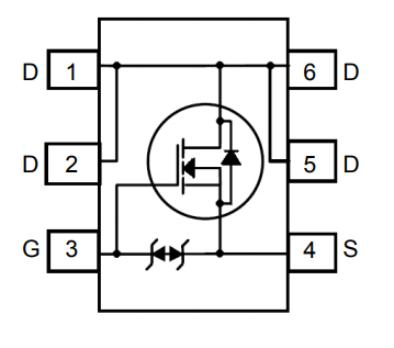
"M801" hints at a MOSFETMOSFET. There is a "Q301" so if it was a bipolar transistor, they'd have used a "Q" designator. Also, a MOSFET fits with my "PWM the motor" hypothesis. And the "801" hints that the designer perhaps thought it was part of the same bit of circuit than the diodes.

The squiggly trace isn't an antenna, since the device is a razor, it doesn't have radio. I'm betting on a cheapo way to implement a low value (milliohms) resistor for motor current sensing, or maybe add a bit of inductance for EMI purposes, who knows.

Also, if we have a MOSFET and a flywheel diode... and you inverted the supply voltage polarity... then both diodes were in series and shorting the supply, so the FET popped, which makes sense.

So I'll bet on a MOSFET. You still have to identify its polarity, get a rough idea on RdsON, and decide whether it's single or maybe dual !

First thing to do would be tois check if the rest of the circuit still works. So, desolder itthe FET. Test D802 and desolder it if it is shorted too.

Then try to power up the razor. If you get no smoke and some kind of life signs, like LEDs blinking or whatever, then good news, the micro isn't fried... you can try to probe pins with a scope, see if you find a clock or something. The idea is to check if the circuit is still good before spending time on replacing the FET.

After removing the burned FET, next thing to do would be to check the PCB connections between its pins, to try to confirm it is a single FET. You'll get the polarity by checking how it is connected with the supply and the diode. It's probably N, but who knows. If you have a scope, check the gate to get an idea of switching frequency, then check the motor's resistance and current, then pic a FET that will do the job.

enter image description here

Let's review the evidence...

"D801" and "D802" are wired in parallel, but only one is populated. This hints at power diodes, designers thought maybe two would be required to take the required current, but one ended up being enough so they only populated D802. So we're probably looking at the circuitry that PWMs the razor's motor, and D802 is the flywheel diode.

"M801" hints at a MOSFET. There is a "Q301" so if it was a bipolar transistor, they'd have used a "Q" designator. Also, a MOSFET fits with my "PWM the motor" hypothesis. And the "801" hints that the designer perhaps thought it was part of the same bit of circuit than the diodes.

The squiggly trace isn't an antenna, since the device is a razor, it doesn't have radio. I'm betting on a cheapo way to implement a low value (milliohms) resistor for motor current sensing, or maybe add a bit of inductance for EMI purposes, who knows.

Also, if we have a MOSFET and a flywheel diode... and you inverted the supply voltage polarity... then both diodes were in series and shorting the supply, so the FET popped, which makes sense.

So I'll bet on a MOSFET. You still have to identify its polarity, get a rough idea on RdsON, and decide whether it's single or maybe dual !

First thing to do would be to desolder it. Test D802 and desolder it if it is shorted too.

Then try to power up the razor. If you get no smoke and some kind of life signs, like LEDs blinking or whatever, then good news, the micro isn't fried... you can try to probe pins with a scope, see if you find a clock or something. The idea is to check if the circuit is still good before spending time on replacing the FET.

After removing the burned FET, next thing to do would be to check the PCB connections between its pins, to try to confirm it is a single FET. You'll get the polarity by checking how it is connected with the supply and the diode. It's probably N, but who knows. If you have a scope, check the gate to get an idea of switching frequency, then check the motor's resistance and current, then pic a FET that will do the job.

enter image description here

Let's review the evidence...

"D801" and "D802" are wired in parallel, but only one is populated. This hints at power diodes, designers thought maybe two would be required to take the required current, but one ended up being enough so they only populated D802. So we're probably looking at the circuitry that PWMs the razor's motor, and D802 is the flywheel diode.

"M801" hints at a MOSFET. There is a "Q301" so if it was a bipolar transistor, they'd have used a "Q" designator. Also, a MOSFET fits with my "PWM the motor" hypothesis. And the "801" hints that the designer perhaps thought it was part of the same bit of circuit than the diodes.

The squiggly trace isn't an antenna, since the device is a razor, it doesn't have radio. I'm betting on a cheapo way to implement a low value (milliohms) resistor for motor current sensing, or maybe add a bit of inductance for EMI purposes, who knows.

Also, if we have a MOSFET and a flywheel diode... and you inverted the supply voltage polarity... then both diodes were in series and shorting the supply, so the FET popped, which makes sense.

So I'll bet on a MOSFET. You still have to identify its polarity, get a rough idea on RdsON, and decide whether it's single or maybe dual !

First thing to do is check if the rest of the circuit still works. So, desolder the FET. Test D802 and desolder it if it is shorted too.

Then try to power up the razor. If you get no smoke and some kind of life signs, like LEDs blinking or whatever, then good news, the micro isn't fried... you can try to probe pins with a scope, see if you find a clock or something. The idea is to check if the circuit is still good before spending time on replacing the FET.

After removing the burned FET, next thing to do would be to check the PCB connections between its pins, to try to confirm it is a single FET. You'll get the polarity by checking how it is connected with the supply and the diode. It's probably N, but who knows. If you have a scope, check the gate to get an idea of switching frequency, then check the motor's resistance and current, then pic a FET that will do the job.

enter image description here

Source Link
bobflux
  • 81.6k
  • 3
  • 97
  • 236

Let's review the evidence...

"D801" and "D802" are wired in parallel, but only one is populated. This hints at power diodes, designers thought maybe two would be required to take the required current, but one ended up being enough so they only populated D802. So we're probably looking at the circuitry that PWMs the razor's motor, and D802 is the flywheel diode.

"M801" hints at a MOSFET. There is a "Q301" so if it was a bipolar transistor, they'd have used a "Q" designator. Also, a MOSFET fits with my "PWM the motor" hypothesis. And the "801" hints that the designer perhaps thought it was part of the same bit of circuit than the diodes.

The squiggly trace isn't an antenna, since the device is a razor, it doesn't have radio. I'm betting on a cheapo way to implement a low value (milliohms) resistor for motor current sensing, or maybe add a bit of inductance for EMI purposes, who knows.

Also, if we have a MOSFET and a flywheel diode... and you inverted the supply voltage polarity... then both diodes were in series and shorting the supply, so the FET popped, which makes sense.

So I'll bet on a MOSFET. You still have to identify its polarity, get a rough idea on RdsON, and decide whether it's single or maybe dual !

First thing to do would be to desolder it. Test D802 and desolder it if it is shorted too.

Then try to power up the razor. If you get no smoke and some kind of life signs, like LEDs blinking or whatever, then good news, the micro isn't fried... you can try to probe pins with a scope, see if you find a clock or something. The idea is to check if the circuit is still good before spending time on replacing the FET.

After removing the burned FET, next thing to do would be to check the PCB connections between its pins, to try to confirm it is a single FET. You'll get the polarity by checking how it is connected with the supply and the diode. It's probably N, but who knows. If you have a scope, check the gate to get an idea of switching frequency, then check the motor's resistance and current, then pic a FET that will do the job.

enter image description here