edited body
Source Link
User323693
  • 9.5k
  • 4
  • 22
  • 51

will the voltage across both resistors be the supply minus the .7v drop of the LED?

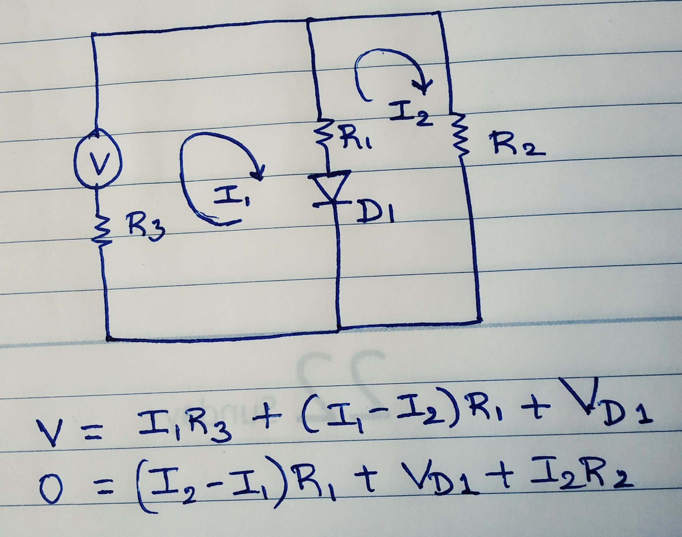
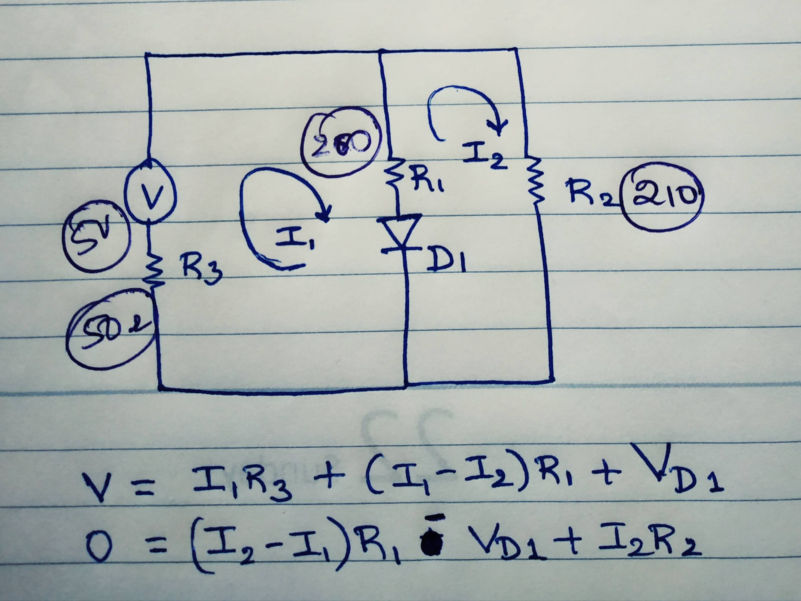
No. You have drawn a nice schematics. The R2 resistor is direklty in parallel to the source voltage. So the voltage across the resistor will be same as the source voltage.

  1. Proceed in this way. R2 is directly in parallel with the source voltage. Hence the voltage has to be the same as source Voltage
  2. For R1, there are two components in series. The diode drop plus the drop across the resistor R1 has to be same as the supply voltage.
  3. The voltage across the diode depends on many factors one of which will be the supply voltage itself and the other will be the forward Voltage of the LED. (About 2.4 V upto 4 V depending on the type of the LED, but definitely not 0.7 V as in normal diodes).

If there are two sides in parallel, the diode with the lower forward Voltage drop turns on first there by keeping he voltage across the second diode too lower than the forward Voltage drop of the second diode. Hence the second diode will not turn on (completely).


  • Start with the loop equations. Except I1 and I2 other parameters are constant and can be solved. I would approach the problem in this way.
enter image description hereenter image description here

will the voltage across both resistors be the supply minus the .7v drop of the LED?

No. You have drawn a nice schematics. The R2 resistor is direklty in parallel to the source voltage. So the voltage across the resistor will be same as the source voltage.

  1. Proceed in this way. R2 is directly in parallel with the source voltage. Hence the voltage has to be the same as source Voltage
  2. For R1, there are two components in series. The diode drop plus the drop across the resistor R1 has to be same as the supply voltage.
  3. The voltage across the diode depends on many factors one of which will be the supply voltage itself and the other will be the forward Voltage of the LED. (About 2.4 V upto 4 V depending on the type of the LED, but definitely not 0.7 V as in normal diodes).

If there are two sides in parallel, the diode with the lower forward Voltage drop turns on first there by keeping he voltage across the second diode too lower than the forward Voltage drop of the second diode. Hence the second diode will not turn on (completely).


  • Start with the loop equations. Except I1 and I2 other parameters are constant and can be solved. I would approach the problem in this way.

enter image description here

added 1 character in body
Source Link
User323693
  • 9.5k
  • 4
  • 22
  • 51

will the voltage across both resistors be the supply minus the .7v drop of the LED?

No. You have drawn a nice schematics. The R2 resistor is direklty in parallel to the source voltage. So the voltage across the resistor will be same as the source voltage.

  1. Proceed in this way. R2 is directly in parallel with hethe source voltage. Hence the voltage has to be the same as sprucesource Voltage
  2. For R1, there are two components in series. The diode drop plus the drop across the resistor R1 has to be same as the supply voltage.
  3. The voltage across the diode depends on many factors one of which will be the supply voltage itself and the other will be the forward Voltage of the LED. (About 2.4 V upto 4 V depending on the type of the LED, but definitely not 0.7 V as in normal diodes).

If there are two sides in parallel, the diode with the lower forward Voltage drop turns on first there by keeping he voltage across the second diode too lower than the forward Voltage drop of the second diode. Hence the second diode will not turn on (completely).


  • Start with the loop equations. Except I1 and I2 other parameters are constant and can be solved. I would approach the problem in this way.

enter image description here

will the voltage across both resistors be the supply minus the .7v drop of the LED?

No. You have drawn a nice schematics. The R2 resistor is direklty in parallel to the source voltage. So the voltage across the resistor will be same as the source voltage.

  1. Proceed in this way. R2 is directly in parallel with he source voltage. Hence the voltage has to be the same as spruce Voltage
  2. For R1, there are two components in series. The diode drop plus the drop across the resistor R1 has to be same as the supply voltage.
  3. The voltage across the diode depends on many factors one of which will be the supply voltage itself and the other will be the forward Voltage of the LED. (About 2.4 V upto 4 V depending on the type of the LED, but definitely not 0.7 V as in normal diodes).

If there are two sides in parallel, the diode with the lower forward Voltage drop turns on first there by keeping he voltage across the second diode too lower than the forward Voltage drop of the second diode. Hence the second diode will not turn on (completely).


  • Start with the loop equations. Except I1 and I2 other parameters are constant and can be solved. I would approach the problem in this way.

enter image description here

will the voltage across both resistors be the supply minus the .7v drop of the LED?

No. You have drawn a nice schematics. The R2 resistor is direklty in parallel to the source voltage. So the voltage across the resistor will be same as the source voltage.

  1. Proceed in this way. R2 is directly in parallel with the source voltage. Hence the voltage has to be the same as source Voltage
  2. For R1, there are two components in series. The diode drop plus the drop across the resistor R1 has to be same as the supply voltage.
  3. The voltage across the diode depends on many factors one of which will be the supply voltage itself and the other will be the forward Voltage of the LED. (About 2.4 V upto 4 V depending on the type of the LED, but definitely not 0.7 V as in normal diodes).

If there are two sides in parallel, the diode with the lower forward Voltage drop turns on first there by keeping he voltage across the second diode too lower than the forward Voltage drop of the second diode. Hence the second diode will not turn on (completely).


  • Start with the loop equations. Except I1 and I2 other parameters are constant and can be solved. I would approach the problem in this way.

enter image description here

added 234 characters in body
Source Link
User323693
  • 9.5k
  • 4
  • 22
  • 51

will the voltage across both resistors be the supply minus the .7v drop of the LED?

No. You have drawn a nice schematics. The R2 resistor is direklty in parallel to the source voltage. So the voltage across the resistor will be same as the source voltage.

  1. Proceed in this way. R2 is directly in parallel with he source voltage. Hence the voltage has to be the same as spruce Voltage
  2. For R1, there are two components in series. The diode drop plus the drop across the resistor R1 has to be same as the supply voltage.
  3. The voltage across the diode depends on many factors one of which will be the supply voltage itself and the other will be the forward Voltage of the LED. (About 2.4 V upto 4 V depending on the type of the LED, but definitely not 0.7 V as in normal diodes).

If there are two sides in parallel, the diode with the lower forward Voltage drop turns on first there by keeping he voltage across the second diode too lower than the forward Voltage drop of the second diode. Hence the second diode will not turn on (completely).


  • Start with the loop equations. Except I1 and I2 other parameters are constant and can be solved. I would approach the problem in this way.

enter image description here

will the voltage across both resistors be the supply minus the .7v drop of the LED?

No. You have drawn a nice schematics. The R2 resistor is direklty in parallel to the source voltage. So the voltage across the resistor will be same as the source voltage.

  1. Proceed in this way. R2 is directly in parallel with he source voltage. Hence the voltage has to be the same as spruce Voltage
  2. For R1, there are two components in series. The diode drop plus the drop across the resistor R1 has to be same as the supply voltage.
  3. The voltage across the diode depends on many factors one of which will be the supply voltage itself and the other will be the forward Voltage of the LED. (About 2.4 V upto 4 V depending on the type of the LED, but definitely not 0.7 V as in normal diodes).

If there are two sides in parallel, the diode with the lower forward Voltage drop turns on first there by keeping he voltage across the second diode too lower than the forward Voltage drop of the second diode. Hence the second diode will not turn on (completely).


  • Start with the loop equations. Except I1 and I2 other parameters are constant and can be solved. I would approach the problem in this way.

enter image description here

added 762 characters in body; added 46 characters in body
Source Link
User323693
  • 9.5k
  • 4
  • 22
  • 51
Loading
Source Link
User323693
  • 9.5k
  • 4
  • 22
  • 51
Loading