added 192 characters in body
Source Link

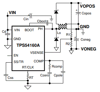
I'm trying to build a DC-DCDC-DC split-rail converter using circuit from this article:

enter image description here

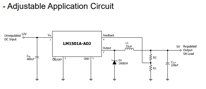
. My goal is to split 12..14V12..14V input voltage into +2.4V+2.4V and -2.4V-2.4V. To do that, I usechoosed LM1501AGR-ADJ IC, which allows to get output voltage from 1.23V to 37V. The circuit from its datasheet looks like that:

enter image description here

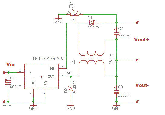
I calculated the needed inductance value (15 uH15 uH) and made the coupled inductor, and then built the following circuit:

enter image description here

UnfortunatelyIt works OK, it does not work. Whenbut only when I apply input voltagea certain load. When the load is (12V)1K or more, Vout-Vout- is about -11V-11V, and Vout+Vout+ is -0.2V. Adjusting-0.2V R1 affects only on(input voltage is Vout-12V). Load resistance of - it's minimum value that I was able220R or less makes Vout- equal to obtain is -5.0V.-2.39V, and Vout+ does not change at all. All measurements were made without any loadVout+ to 2.36V, which is just fine for my purposes.

Is this even possibleI don't like the fact that circuit needs some "dummy" load to make such converter?work correctly, because it means aditional power consumption. I'm gonna use battery as the power supply, so I triedwhant it to build something like this using LM317 and LM337consume as less power as possible. Besides, but it heats too much @2A output currentlooks like a very quick'n'dirty solution. Are there better ways to solve this problem?

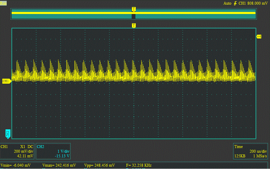
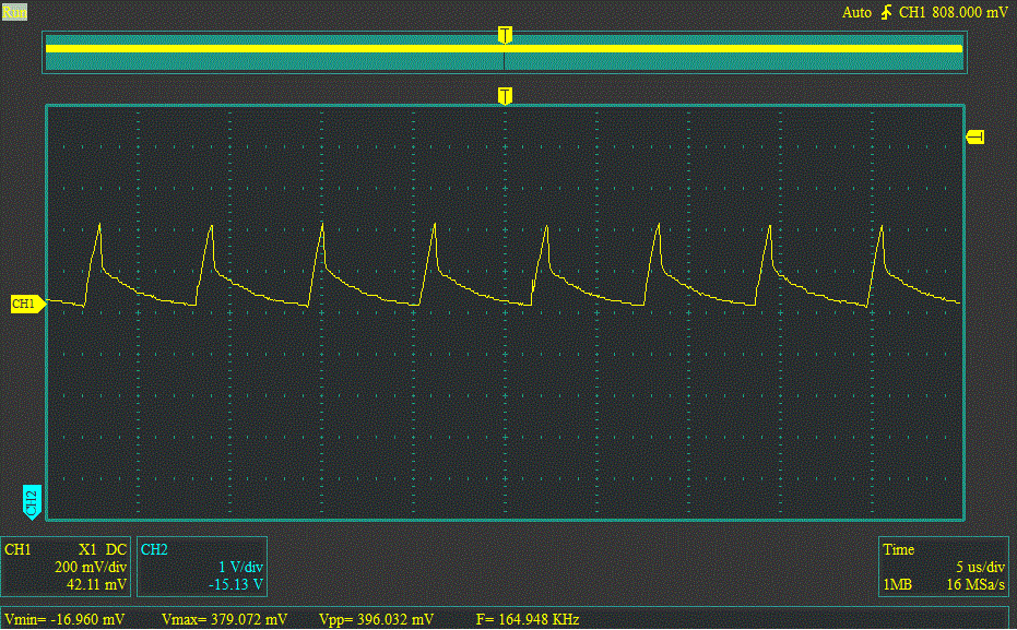
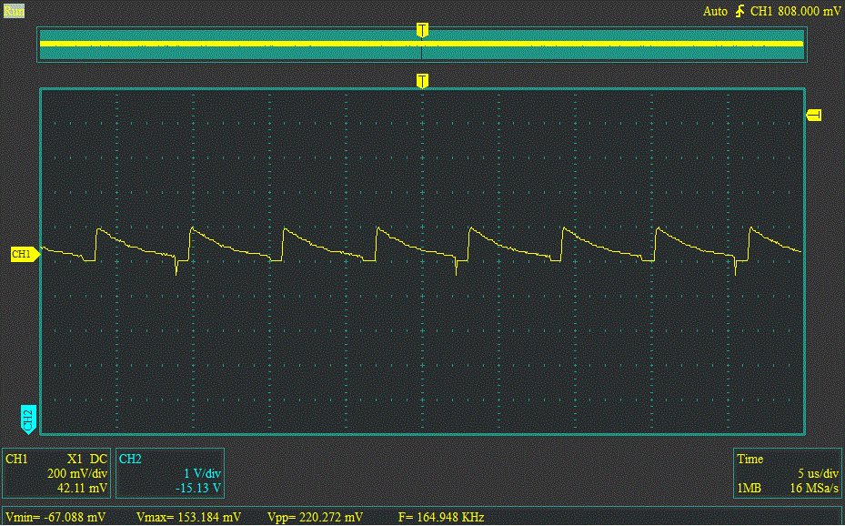
UPD:To provide some additional information about the circuit, I have tried to add aobtain the inductor's currents waveforms. To do that, I removed 1K load resistors for bothC2 and Vout+C3 and `Vout- outputsapplied the load resistors - nothing changed10R, than measured the voltage waveform on them. Here is what I use SB560 diodesgot:

Primary coil

Primary coil

Primary coil - large scale

Primary coil - maybe they are not good choise?large scale

Secondary coil

Secondary coil

By primary coil I mean the coil which is connected directly to IC.

I'm trying to build a DC-DC split-rail converter using circuit from this article:

enter image description here

My goal is to split 12..14V input voltage into +2.4V and -2.4V. To do that, I use LM1501AGR-ADJ IC, which allows to get output voltage from 1.23V to 37V. The circuit from its datasheet looks like that:

enter image description here

I calculated the needed inductance value (15 uH) and made the coupled inductor, and then built the following circuit:

enter image description here

Unfortunately, it does not work. When I apply input voltage (12V), Vout- is about -11V, and Vout+ is -0.2V. Adjusting R1 affects only on Vout- - it's minimum value that I was able to obtain is -5.0V. Vout+ does not change at all. All measurements were made without any load.

Is this even possible to make such converter? I tried to build something like this using LM317 and LM337, but it heats too much @2A output current.

UPD: I have tried to add a 1K load resistors for both Vout+ and `Vout- outputs - nothing changed. I use SB560 diodes - maybe they are not good choise?

I'm trying to build a DC-DC split-rail converter using circuit from this article. My goal is to split 12..14V input voltage into +2.4V and -2.4V. To do that, I choosed LM1501AGR-ADJ IC, calculated the needed inductance value (15 uH) and made the coupled inductor, then built the following circuit:

enter image description here

It works OK, but only when I apply a certain load. When the load is 1K or more, Vout- is about -11V, and Vout+ is -0.2V (input voltage is 12V). Load resistance of 220R or less makes Vout- equal to -2.39V, and Vout+ to 2.36V, which is just fine for my purposes.

I don't like the fact that circuit needs some "dummy" load to work correctly, because it means aditional power consumption. I'm gonna use battery as the power supply, so I whant it to consume as less power as possible. Besides, it looks like a very quick'n'dirty solution. Are there better ways to solve this problem?

To provide some additional information about the circuit, I tried to obtain the inductor's currents waveforms. To do that, I removed C2 and C3 and applied the load resistors 10R, than measured the voltage waveform on them. Here is what I got:

Primary coil

Primary coil

Primary coil - large scale

Primary coil - large scale

Secondary coil

Secondary coil

By primary coil I mean the coil which is connected directly to IC.
added 103 characters in body
Source Link

I'm trying to build a DC-DC split-rail converter using circuit from this article:

enter image description here

My goal is to split 12..14V input voltage into +2.4V and -2.4V. To do that, I use LM1501AGR-ADJ IC, which allows to get output voltage from 1.23V to 37V. The circuit from its datasheet looks like that:

enter image description here

I calculated the needed inductance value (15 uH) and made the coupled inductor, and then built the following circuit:

enter image description here

Unfortunately, it does not work. When I apply input voltage (12V), Vout- is about -11V, and Vout+ is -0.2V. Adjusting R1 affects only on Vout- - it's minimum value that I was able to obtain is -5.0V. Vout+ does not change at all. All measurements were made without any load.

Is this even possible to make such converter? I tried to build something like this using LM317 and LM337, but it heats too much @2A output current.

UPD: I have tried to add a 1K load resistors for both Vout+ and `Vout- outputs - nothing changed. I use SB560 diodes - maybe they are not good choise?

I'm trying to build a DC-DC split-rail converter using circuit from this article:

enter image description here

My goal is to split 12..14V input voltage into +2.4V and -2.4V. To do that, I use LM1501AGR-ADJ IC, which allows to get output voltage from 1.23V to 37V. The circuit from its datasheet looks like that:

enter image description here

I calculated the needed inductance value (15 uH) and made the coupled inductor, and then built the following circuit:

enter image description here

Unfortunately, it does not work. When I apply input voltage (12V), Vout- is about -11V, and Vout+ is -0.2V. Adjusting R1 affects only on Vout- - it's minimum value that I was able to obtain is -5.0V. Vout+ does not change at all. All measurements were made without any load.

Is this even possible to make such converter? I tried to build something like this using LM317 and LM337, but it heats too much @2A output current.

UPD: I have tried to add a 1K load resistors for both Vout+ and `Vout- outputs - nothing changed. I use SB560 diodes - maybe they are not good choise?

Source Link

DC/DC split rail converter with coupled inductor

I'm trying to build a DC-DC split-rail converter using circuit from this article:

enter image description here

My goal is to split 12..14V input voltage into +2.4V and -2.4V. To do that, I use LM1501AGR-ADJ IC, which allows to get output voltage from 1.23V to 37V. The circuit from its datasheet looks like that:

enter image description here

I calculated the needed inductance value (15 uH) and made the coupled inductor, and then built the following circuit:

enter image description here

Unfortunately, it does not work. When I apply input voltage (12V), Vout- is about -11V, and Vout+ is -0.2V. Adjusting R1 affects only on Vout- - it's minimum value that I was able to obtain is -5.0V. Vout+ does not change at all. All measurements were made without any load.

Is this even possible to make such converter? I tried to build something like this using LM317 and LM337, but it heats too much @2A output current.