added 1233 characters in body
Source Link

The easiest approach I have found and used is with just two inverters:
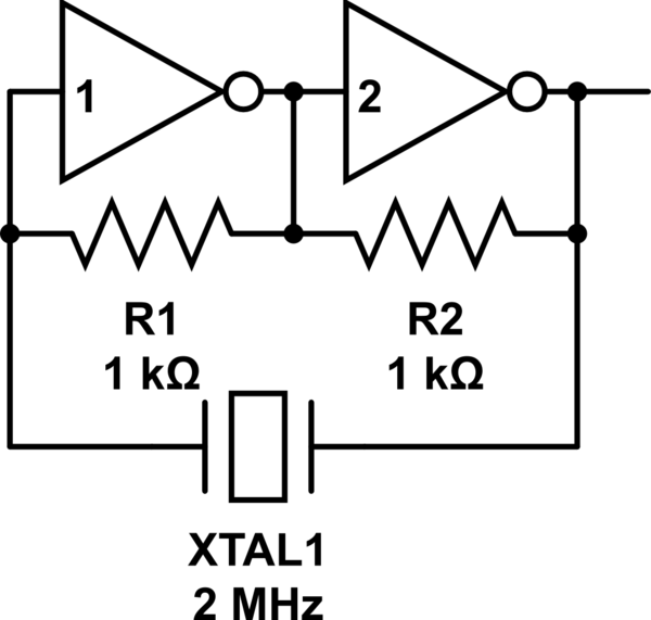
schematic

simulate this circuit – Schematic created using CircuitLab

I have built this with a 74LS04 with no problem at all. It is trivial. No calculations of RC networks required. 2MHz and 4MHz both worked. I am going to experiment with a Schmitt trigger-inverter to follow to see if that makes the wave more of a rectangle.

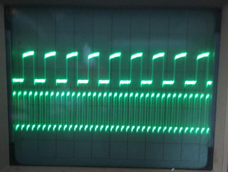
My scope picture shows what I am getting and I use a 74LS161 counter to divide the frequency down and I see the forms are all the same: a little down spike right before the rising edge and then a bit of an up-slope of the roof of the wave. I think that's mostly determined by my use of bread board.

enter image description here

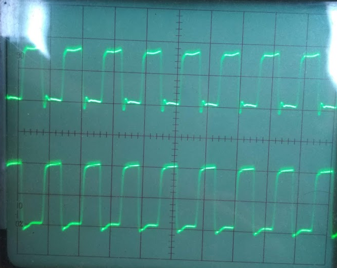
UPDATE: Here are the results of another experiment where I follow this simple clock generator with a Schmitt-trigger to see if it forms any prettier rectangles. Above the output of a regular additional inverter stage, and below if that additional inverter stage is a Schmitt-trigger. If anything the regular inverter produces prettier rectangles.

enter image description here

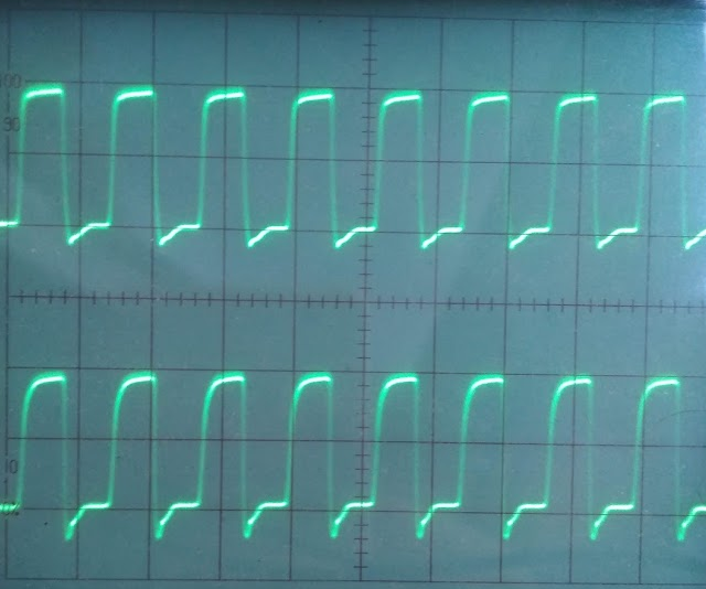
Here is the direct output from the inverter 2 of the oscillator vs. the output of an additional regular inverter. Cleans up this overshooting down-stroke a little.

enter image description here

One thing that makes me puzzled is the frequency I am getting here. I don't know if my calculations are off, but it looks to me that the period duration is just a little over one scope division, and to be more exact I have pretty exactly 4 periods in 5 scope divisions. And the setting is at 0.1 μs per division, so that would mean 0.5 μs / 4 periods or T = 0.125 μs, for an f = 8 MHz! How can it be that a 2 MHz crystal produces 8 MHz oscillations? This is very puzzling. It means I need to try out other circuits to understand this.

The easiest approach I have found and used is with just two inverters:

schematic

simulate this circuit – Schematic created using CircuitLab

I have built this with a 74LS04 with no problem at all. It is trivial. No calculations of RC networks required. 2MHz and 4MHz both worked. I am going to experiment with a Schmitt trigger-inverter to follow to see if that makes the wave more of a rectangle.

My scope picture shows what I am getting and I use a 74LS161 counter to divide the frequency down and I see the forms are all the same: a little down spike right before the rising edge and then a bit of an up-slope of the roof of the wave. I think that's mostly determined by my use of bread board.

enter image description here

UPDATE: Here are the results of another experiment where I follow this simple clock generator with a Schmitt-trigger to see if it forms any prettier rectangles. Above the output of a regular additional inverter stage, and below if that additional inverter stage is a Schmitt-trigger. If anything the regular inverter produces prettier rectangles.

enter image description here

Here is the direct output from the inverter 2 of the oscillator vs. the output of an additional regular inverter. Cleans up this overshooting down-stroke a little.

enter image description here

One thing that makes me puzzled is the frequency I am getting here. I don't know if my calculations are off, but it looks to me that the period duration is just a little over one scope division, and to be more exact I have pretty exactly 4 periods in 5 scope divisions. And the setting is at 0.1 μs per division, so that would mean 0.5 μs / 4 periods or T = 0.125 μs, for an f = 8 MHz! How can it be that a 2 MHz crystal produces 8 MHz oscillations? This is very puzzling. It means I need to try out other circuits to understand this.
Source Link

The easiest approach I have found and used is with just two inverters:

schematic

simulate this circuit – Schematic created using CircuitLab

I have built this with a 74LS04 with no problem at all. It is trivial. No calculations of RC networks required. 2MHz and 4MHz both worked. I am going to experiment with a Schmitt trigger-inverter to follow to see if that makes the wave more of a rectangle.

My scope picture shows what I am getting and I use a 74LS161 counter to divide the frequency down and I see the forms are all the same: a little down spike right before the rising edge and then a bit of an up-slope of the roof of the wave. I think that's mostly determined by my use of bread board.

enter image description here