Italics, first line.
Source Link
user105652
user105652

The input impedance of a CMOS logic gate iscan be over 100 Mohms, but you do not want a high resistive value unless this is battery powered. Normally to keep sensitivity to noise down the resistor would be from 10 K ohm to 100 K ohm.

A 10 K pull-down means when the switch is closed the resistor is draining 500 uA of current, and the 100 K would drain 50 uA of current. 1 megohm would draw just 5 uA of current but the high impedance would make the input sensitive to local noise and at elevated temperatures gate leakage could be an issue.

If you have a choice in the matter the 10 K is the best option, but if this is battery powered and every uA counts then use 100 K pull-downs. To cut way down on noise sensitivity you can parallel a 10 nF or 100 nF capacitor with the pull-down resistor.

The following is a basic digital input filter / clamp with pull-down resistor. Theses can be tiny SMD parts that take up little space.
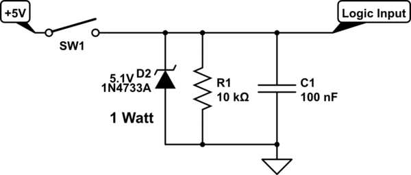
schematic

simulate this circuit – Schematic created using CircuitLab

The input impedance of a CMOS logic gate is over 100 Mohms, but you do not want a high resistive value unless this is battery powered. Normally to keep sensitivity to noise down the resistor would be from 10 K ohm to 100 K ohm.

A 10 K pull-down means when the switch is closed the resistor is draining 500 uA of current, and the 100 K would drain 50 uA of current. 1 megohm would draw just 5 uA of current but the high impedance would make the input sensitive to local noise and at elevated temperatures gate leakage could be an issue.

If you have a choice in the matter the 10 K is the best option, but if this is battery powered and every uA counts then use 100 K pull-downs. To cut way down on noise sensitivity you can parallel a 10 nF or 100 nF capacitor with the pull-down resistor.

The following is a basic digital input filter / clamp with pull-down resistor. Theses can be tiny SMD parts that take up little space.

schematic

simulate this circuit – Schematic created using CircuitLab
The input impedance of a CMOS logic gate can be over 100 Mohms, but you do not want a high resistive value unless this is battery powered. Normally to keep sensitivity to noise down the resistor would be from 10 K ohm to 100 K ohm.

A 10 K pull-down means when the switch is closed the resistor is draining 500 uA of current, and the 100 K would drain 50 uA of current. 1 megohm would draw just 5 uA of current but the high impedance would make the input sensitive to local noise and at elevated temperatures gate leakage could be an issue.

If you have a choice in the matter the 10 K is the best option, but if this is battery powered and every uA counts then use 100 K pull-downs. To cut way down on noise sensitivity you can parallel a 10 nF or 100 nF capacitor with the pull-down resistor.

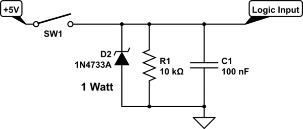
The following is a basic digital input filter / clamp with pull-down resistor. Theses can be tiny SMD parts that take up little space.

schematic

simulate this circuit – Schematic created using CircuitLab

Added 5.1V to diode
Source Link
user105652
user105652

The input impedance of a CMOS logic gate is over 100 Mohms, but you do not want a high resistive value unless this is battery powered. Normally to keep sensitivity to noise down the resistor would be from 10 K ohm to 100 K ohm.

A 10 K pull-down means when the switch is closed the resistor is draining 500 uA of current, and the 100 K would drain 50 uA of current. 1 megohm would draw just 5 uA of current but the high impedance would make the input sensitive to local noise and at elevated temperatures gate leakage could be an issue.

If you have a choice in the matter the 10 K is the best option, but if this is battery powered and every uA counts then use 100 K pull-downs. To cut way down on noise sensitivity you can parallel a 10 nF or 100 nF capacitor with the pull-down resistor.

The following is a basic digital input filter / clamp with pull-down resistor. Theses can be tiny SMD parts that take up little space.

schematicschematic

simulate this circuitsimulate this circuit – Schematic created using CircuitLab

The input impedance of a CMOS logic gate is over 100 Mohms, but you do not want a high resistive value unless this is battery powered. Normally to keep sensitivity to noise down the resistor would be from 10 K ohm to 100 K ohm.

A 10 K pull-down means when the switch is closed the resistor is draining 500 uA of current, and the 100 K would drain 50 uA of current. 1 megohm would draw just 5 uA of current but the high impedance would make the input sensitive to local noise and at elevated temperatures gate leakage could be an issue.

If you have a choice in the matter the 10 K is the best option, but if this is battery powered and every uA counts then use 100 K pull-downs. To cut way down on noise sensitivity you can parallel a 10 nF or 100 nF capacitor with the pull-down resistor.

The following is a basic digital input filter / clamp with pull-down resistor. Theses can be tiny SMD parts that take up little space.

schematic

simulate this circuit – Schematic created using CircuitLab

Added schematic
Source Link
user105652
user105652

The input impedance of a CMOS logic gate is over 100 Mohms, but you do not want a high resistive value unless this is battery powered. Normally to keep sensitivity to noise down the resistor would be from 10 K ohm to 100 K ohm.

A 10 K pull-down means when the switch is closed the resistor is draining 500 uA of current, and the 100 K would drain 50 uA of current. 1 megohm would draw just 5 uA of current but the high impedance would make the input sensitive to local noise and at elevated temperatures gate leakage could be an issue.

If you have a choice in the matter the 10 K is the best option, but if this is battery powered and every uA counts then use 100 K pull-downs. To cut way down on noise sensitivity you can parallel a 10 nF or 100 nF capacitor with the pull-down resistor.

The following is a basic digital input filter / clamp with pull-down resistor. Theses can be tiny SMD parts that take up little space.

schematic

simulate this circuit – Schematic created using CircuitLab

The input impedance of a CMOS logic gate is over 100 Mohms, but you do not want a high resistive value unless this is battery powered. Normally to keep sensitivity to noise down the resistor would be from 10 K ohm to 100 K ohm.

A 10 K pull-down means when the switch is closed the resistor is draining 500 uA of current, and the 100 K would drain 50 uA of current. 1 megohm would draw just 5 uA of current but the high impedance would make the input sensitive to local noise and at elevated temperatures gate leakage could be an issue.

If you have a choice in the matter the 10 K is the best option, but if this is battery powered and every uA counts then use 100 K pull-downs. To cut way down on noise sensitivity you can parallel a 10 nF or 100 nF capacitor with the pull-down resistor.

The following is a basic digital input filter / clamp with pull-down resistor. Theses can be tiny SMD parts that take up little space.

schematic

simulate this circuit – Schematic created using CircuitLab

Added to 2nd paragraph.
Source Link
user105652
user105652
Loading
Source Link
user105652
user105652
Loading