Notice removed Draw attention by SukkoPera
Bounty Ended with metacollin's answer chosen by SukkoPera
Notice added Draw attention by SukkoPera
Bounty Started worth 50 reputation by SukkoPera
added 169 characters in body
Source Link
SukkoPera
  • 191
  • 1
  • 13

I am using the Microchip ENC28J60 Ethernet Controller in a microcontroller design.

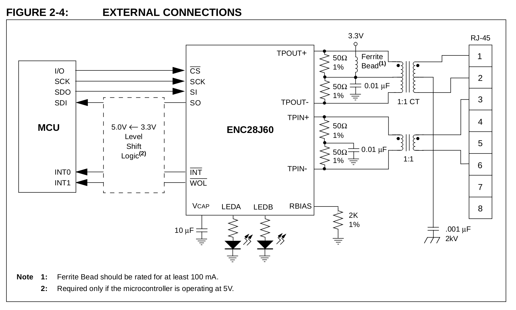
The datasheet contains the following reference circuit:

enter image description here

I am designing a custom PCB, getting inspiration from a sample Chinese board I am doing my development with, which contains the chip, magjack and a few more components. I have traced it to be an almost 1:1 implementation of the above reference design, but there is a difference, being that pin 5 of the Ethernet jack is connected to the midpoint of the 50R resistors on the receive side (TPIN+/-), where the 0.01uF cap is also connected.

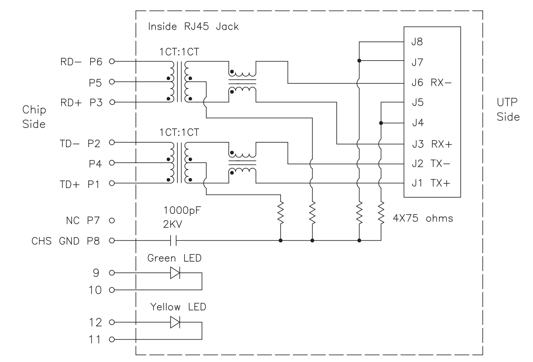
Pin 5 comes from the center tap of the receive transformer, as follows:

http://ww1.microchip.com/downloads/en/DeviceDoc/39662e.pdf

So first question: Is this an error on my board or something I should put in my design?

Second question: what ferrite bead am I supposed to use in the transmit circuit? I couldn't find any reference to the required 100MHz impedance in the datasheet.

Another question is about the magjack (HANRUN HR911105A), whose datasheet has the following note: Connect CHS GND to PCB ground. This would be pin 8, but it is left unconnected on my board. Should I connect it?

Also, I guess "CHS ground" is "chassis ground". Does this mean it's connected to the outside metal shield of the magjack? I'm asking, because the shield gets into two holes on the PCB, which are connected to ground on my board but they are not actually soldered, and the metal tab just hangs in the hole without touching its sides. Should i ground it?

Thanks a lot!

I am using the Microchip ENC28J60 Ethernet Controller in a microcontroller design.

The datasheet contains the following reference circuit:

enter image description here

I am designing a custom PCB, getting inspiration from a sample Chinese board I am doing my development with, which contains the chip, magjack and a few more components. I have traced it to be an almost 1:1 implementation of the above reference design, but there is a difference, being that pin 5 of the Ethernet jack is connected to the midpoint of the 50R resistors on the receive side (TPIN+/-), where the 0.01uF cap is also connected.

Pin 5 comes from the center tap of the receive transformer, as follows:

http://ww1.microchip.com/downloads/en/DeviceDoc/39662e.pdf

So first question: Is this an error on my board or something I should put in my design?

Another question is about the magjack (HANRUN HR911105A), whose datasheet has the following note: Connect CHS GND to PCB ground. This would be pin 8, but it is left unconnected on my board. Should I connect it?

Also, I guess "CHS ground" is "chassis ground". Does this mean it's connected to the outside metal shield of the magjack? I'm asking, because the shield gets into two holes on the PCB, which are connected to ground on my board but they are not actually soldered, and the metal tab just hangs in the hole without touching its sides. Should i ground it?

Thanks a lot!
I am using the Microchip ENC28J60 Ethernet Controller in a microcontroller design.

The datasheet contains the following reference circuit:

enter image description here

I am designing a custom PCB, getting inspiration from a sample Chinese board I am doing my development with, which contains the chip, magjack and a few more components. I have traced it to be an almost 1:1 implementation of the above reference design, but there is a difference, being that pin 5 of the Ethernet jack is connected to the midpoint of the 50R resistors on the receive side (TPIN+/-), where the 0.01uF cap is also connected.

Pin 5 comes from the center tap of the receive transformer, as follows:

http://ww1.microchip.com/downloads/en/DeviceDoc/39662e.pdf

So first question: Is this an error on my board or something I should put in my design?

Second question: what ferrite bead am I supposed to use in the transmit circuit? I couldn't find any reference to the required 100MHz impedance in the datasheet.

Another question is about the magjack (HANRUN HR911105A), whose datasheet has the following note: Connect CHS GND to PCB ground. This would be pin 8, but it is left unconnected on my board. Should I connect it?

Also, I guess "CHS ground" is "chassis ground". Does this mean it's connected to the outside metal shield of the magjack? I'm asking, because the shield gets into two holes on the PCB, which are connected to ground on my board but they are not actually soldered, and the metal tab just hangs in the hole without touching its sides. Should i ground it?

Thanks a lot!
Source Link
SukkoPera
  • 191
  • 1
  • 13

Proper use of the ENC28J60 Ethernet controller

I am using the Microchip ENC28J60 Ethernet Controller in a microcontroller design.

The datasheet contains the following reference circuit:

enter image description here

I am designing a custom PCB, getting inspiration from a sample Chinese board I am doing my development with, which contains the chip, magjack and a few more components. I have traced it to be an almost 1:1 implementation of the above reference design, but there is a difference, being that pin 5 of the Ethernet jack is connected to the midpoint of the 50R resistors on the receive side (TPIN+/-), where the 0.01uF cap is also connected.

Pin 5 comes from the center tap of the receive transformer, as follows:

http://ww1.microchip.com/downloads/en/DeviceDoc/39662e.pdf

So first question: Is this an error on my board or something I should put in my design?

Another question is about the magjack (HANRUN HR911105A), whose datasheet has the following note: Connect CHS GND to PCB ground. This would be pin 8, but it is left unconnected on my board. Should I connect it?

Also, I guess "CHS ground" is "chassis ground". Does this mean it's connected to the outside metal shield of the magjack? I'm asking, because the shield gets into two holes on the PCB, which are connected to ground on my board but they are not actually soldered, and the metal tab just hangs in the hole without touching its sides. Should i ground it?

Thanks a lot!