added 68 characters in body
Source Link
boileau
  • 145
  • 6

I'm trying to control 24V solenoids using logic level inputs at 5V. The following circuit works when replacing both power loops with a single 9V battery, except that the voltage across the gate and source is not 0 as expected when the switch is closed.

When attached to the actual components with the correct voltages, the MOSFET always powers the drain, regardless of whether the switch is closed.

Can anyone tell me why the circuit works differently than in the simulation? How can I improve it?
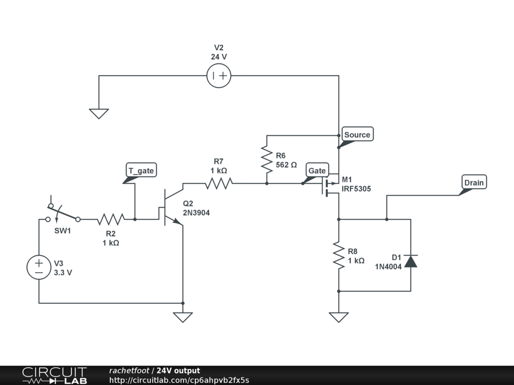
enter image description here https://www.circuitlab.com/circuit/p6ahpvb2fx5s/24v-output/

Edit: The load (solenoid) is represented by R8 in this schematic

I'm trying to control 24V solenoids using logic level inputs at 5V. The following circuit works when replacing both power loops with a single 9V battery, except that the voltage across the gate and source is not 0 as expected when the switch is closed.

When attached to the actual components with the correct voltages, the MOSFET always powers the drain, regardless of whether the switch is closed.

Can anyone tell me why the circuit works differently than in the simulation? How can I improve it?

enter image description here https://www.circuitlab.com/circuit/p6ahpvb2fx5s/24v-output/

Edit: The load (solenoid) is represented by R8 in this schematic

Source Link
boileau
  • 145
  • 6

MOSFET 24V high-side switch

I'm trying to control 24V solenoids using logic level inputs at 5V. The following circuit works when replacing both power loops with a single 9V battery, except that the voltage across the gate and source is not 0 as expected when the switch is closed.

When attached to the actual components with the correct voltages, the MOSFET always powers the drain, regardless of whether the switch is closed.

Can anyone tell me why the circuit works differently than in the simulation? How can I improve it?

enter image description here https://www.circuitlab.com/circuit/p6ahpvb2fx5s/24v-output/