added 1466 characters in body
Source Link
wbs2422
  • 690
  • 1
  • 6
  • 14

I would like to know how do we choose the nodes for a Thevenin Equivalent Circuit.

For example, in the voltage divider, we compute the Thevenin equivalent circuit between the nodes where we would connect our load:
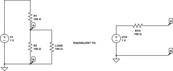
schematic

simulate this circuit – Schematic created using CircuitLab

(do not mind the value of the voltages and components, they are irrelevant for my question in addition to be wrong because I haven't done the calculations).

However, in an amplifier circuit (for example, a simple common-emitter), I do not understand how do we choose the nodes for the equivalent circuit:
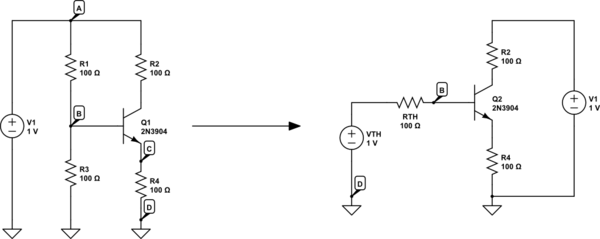
schematic

simulate this circuit

We use for example a thevenin equivalent circuit to easily compute the biasing base current of the transistor. What nodes do we choose for that? As the resulting equivalent circuit is connected between the base and the ground, I assume it was computed between these nodes (nodes B and D), is it correct?

This case is similar to the voltage divider, however what do we consider being our load? As we computed the equivalent circuit between B and D, does it mean that our load is the base-emitter junction along with the emitter resistor?

Why have we not chosen to compute the equivalent circuit between nodes A and B for example? Would it be possible and would we get the same results?

Thank you.

EDIT: after having thought about this and redone the calculations, it seems that the two solutions are equivalent:

Taking the Thevenin equivalent between nodes A and B gives:
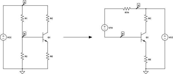
schematic

simulate this circuit

Here we have \$ V_{TH} = \frac{R1}{R1 + R2} V_{CC} \$ and \$ R_{TH} = R1 // R2 \$.

KVL gives us: \$ V_{CC} = R_{TH}.i_b + V_{TH} + V_{BE} + R_E.i_E\$

which can be rewritten as:

$$ \frac{R2}{R1 + R2}.V_{CC} = (R1 // R2).i_b + V_{BE} + R_E.i_E $$

Taking the Thevenin equivalent between nodes B and C gives:

schematic

simulate this circuit

Here we have \$ V_{TH} = \frac{R2}{R1 + R2} V_{CC} \$ and \$ R_{TH} = R1 // R2 \$.

KVL gives us: \$ V_{TH} = R_{TH}.i_b + V_{BE} + R_E.i_E\$

which can be rewritten as:

$$ \frac{R2}{R1 + R2}.V_{CC} = (R1 // R2).i_b + V_{BE} + R_E.i_E $$

This is exactly the same equation as the previous circuit, hence they are both equivalent.

I hope it will help some people, because it really confused me at first.

I would like to know how do we choose the nodes for a Thevenin Equivalent Circuit.

For example, in the voltage divider, we compute the Thevenin equivalent circuit between the nodes where we would connect our load:

schematic

simulate this circuit – Schematic created using CircuitLab

(do not mind the value of the voltages and components, they are irrelevant for my question in addition to be wrong because I haven't done the calculations).

However, in an amplifier circuit (for example, a simple common-emitter), I do not understand how do we choose the nodes for the equivalent circuit:

schematic

simulate this circuit

We use for example a thevenin equivalent circuit to easily compute the biasing base current of the transistor. What nodes do we choose for that? As the resulting equivalent circuit is connected between the base and the ground, I assume it was computed between these nodes (nodes B and D), is it correct?

This case is similar to the voltage divider, however what do we consider being our load? As we computed the equivalent circuit between B and D, does it mean that our load is the base-emitter junction along with the emitter resistor?

Why have we not chosen to compute the equivalent circuit between nodes A and B for example? Would it be possible and would we get the same results?

Thank you.

EDIT: after having thought about this and redone the calculations, it seems that the two solutions are equivalent:

Taking the Thevenin equivalent between nodes A and B gives:

schematic

simulate this circuit

Here we have \$ V_{TH} = \frac{R1}{R1 + R2} V_{CC} \$ and \$ R_{TH} = R1 // R2 \$.

KVL gives us: \$ V_{CC} = R_{TH}.i_b + V_{TH} + V_{BE} + R_E.i_E\$

which can be rewritten as:

$$ \frac{R2}{R1 + R2}.V_{CC} = (R1 // R2).i_b + V_{BE} + R_E.i_E $$

Taking the Thevenin equivalent between nodes B and C gives:

schematic

simulate this circuit

Here we have \$ V_{TH} = \frac{R2}{R1 + R2} V_{CC} \$ and \$ R_{TH} = R1 // R2 \$.

KVL gives us: \$ V_{TH} = R_{TH}.i_b + V_{BE} + R_E.i_E\$

which can be rewritten as:

$$ \frac{R2}{R1 + R2}.V_{CC} = (R1 // R2).i_b + V_{BE} + R_E.i_E $$

This is exactly the same equation as the previous circuit, hence they are both equivalent.

I hope it will help some people, because it really confused me at first.

added 64 characters in body
Source Link
wbs2422
  • 690
  • 1
  • 6
  • 14

I would like to know how do we choose the nodes for a Thevenin Equivalent Circuit.

For example, in the voltage divider, we compute the Thevenin equivalent circuit between the nodes where we would connect our load:

schematic

simulate this circuit – Schematic created using CircuitLab

(do not mind the value of the voltages and components, they are irrelevant for my question in addition to be wrong because I haven't done the calculations).

However, in an amplifier circuit (for example, a simple common-emitter), I do not understand how do we choose the nodes for the equivalent circuit:

schematic

simulate this circuit

We use for example a thevenin equivalent circuit to easily compute the biasing base current of the transistor. What nodes do we choose for that? As the resulting equivalent circuit is connected between the base and the ground, I assume it was computed between these nodes (nodes B and D), is it correct?

This case is similar to the voltage divider, however what do we consider being our load? As we computed the equivalent circuit between B and D, does it mean that our load is the base-emitter junction along with the emitter resistor?

Why have we not chosen to compute the equivalent circuit between nodes A and B for example? Would it be possible and would we get the same results?

Thank you.

I would like to know how do we choose the nodes for a Thevenin Equivalent Circuit.

For example, in the voltage divider, we compute the Thevenin equivalent circuit between the nodes where we would connect our load:

schematic

simulate this circuit – Schematic created using CircuitLab

(do not mind the value of the voltages and components, they are irrelevant for my question).

However, in an amplifier circuit (for example, a simple common-emitter), I do not understand how do we choose the nodes for the equivalent circuit:

schematic

simulate this circuit

We use for example a thevenin equivalent circuit to easily compute the biasing base current of the transistor. What nodes do we choose for that? As the resulting equivalent circuit is connected between the base and the ground, I assume it was computed between these nodes (nodes B and D), is it correct?

This case is similar to the voltage divider, however what do we consider being our load? As we computed the equivalent circuit between B and D, does it mean that our load is the base-emitter junction along with the emitter resistor?

Why have we not chosen to compute the equivalent circuit between nodes A and B for example? Would it be possible and would we get the same results?

Thank you.

I would like to know how do we choose the nodes for a Thevenin Equivalent Circuit.

For example, in the voltage divider, we compute the Thevenin equivalent circuit between the nodes where we would connect our load:

schematic

simulate this circuit – Schematic created using CircuitLab

(do not mind the value of the voltages and components, they are irrelevant for my question in addition to be wrong because I haven't done the calculations).

However, in an amplifier circuit (for example, a simple common-emitter), I do not understand how do we choose the nodes for the equivalent circuit:

schematic

simulate this circuit

We use for example a thevenin equivalent circuit to easily compute the biasing base current of the transistor. What nodes do we choose for that? As the resulting equivalent circuit is connected between the base and the ground, I assume it was computed between these nodes (nodes B and D), is it correct?

This case is similar to the voltage divider, however what do we consider being our load? As we computed the equivalent circuit between B and D, does it mean that our load is the base-emitter junction along with the emitter resistor?

Why have we not chosen to compute the equivalent circuit between nodes A and B for example? Would it be possible and would we get the same results?

Thank you.

Source Link
wbs2422
  • 690
  • 1
  • 6
  • 14

How to choose nodes for Thevenin equivalent circuit

I would like to know how do we choose the nodes for a Thevenin Equivalent Circuit.

For example, in the voltage divider, we compute the Thevenin equivalent circuit between the nodes where we would connect our load:

schematic

simulate this circuit – Schematic created using CircuitLab

(do not mind the value of the voltages and components, they are irrelevant for my question).

However, in an amplifier circuit (for example, a simple common-emitter), I do not understand how do we choose the nodes for the equivalent circuit:

schematic

simulate this circuit

We use for example a thevenin equivalent circuit to easily compute the biasing base current of the transistor. What nodes do we choose for that? As the resulting equivalent circuit is connected between the base and the ground, I assume it was computed between these nodes (nodes B and D), is it correct?

This case is similar to the voltage divider, however what do we consider being our load? As we computed the equivalent circuit between B and D, does it mean that our load is the base-emitter junction along with the emitter resistor?

Why have we not chosen to compute the equivalent circuit between nodes A and B for example? Would it be possible and would we get the same results?

Thank you.