added 404 characters in body
Source Link
Andy aka
  • 472.9k
  • 29
  • 382
  • 839

Instead of the constant source that is fed into the non-inverting input of the 2nd stage op-amp, if I feed in the voltage from the DAC directly, why don’t I see a constant current through Rload?

It won't work as it stands - to make this work you need to make VM2 (the input demand signal voltage) referenced to the positive supply rail (PVDD) so that the op-amp can manipulate its MOSFET in order to make the voltage at the inverting input PVDD minus VM2. In effect, the first circuit relocated VM2 (with a bit of gain change) up at PVDD.

That's what the original circuit did - if RSET and PMIR were equal values then Vin+ of the op-amp equals PVDD - VM2. The fact that RSET and PMIR are different values is just a signal gain change and not about ensuring that the offsets are correct.

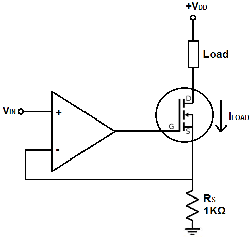
To make this easier to see, consider the constant current sink using an N channel MOSFET: -

enter image description here

The op-amp tries to ensure that the voltage across Rs is the same as Vin.

Turning it upside down and use a P channel MOSFET means that the demand reference point instead of being ground is now the positive rail.

Instead of the constant source that is fed into the non-inverting input of the 2nd stage op-amp, if I feed in the voltage from the DAC directly, why don’t I see a constant current through Rload?

It won't work as it stands - to make this work you need to make VM2 (the input demand signal voltage) referenced to the positive supply rail (PVDD) so that the op-amp can manipulate its MOSFET in order to make the voltage at the inverting input PVDD minus VM2. In effect, the first circuit relocated VM2 (with a bit of gain change) up at PVDD.

That's what the original circuit did - if RSET and PMIR were equal values then Vin+ of the op-amp equals PVDD - VM2. The fact that RSET and PMIR are different values is just a signal gain change and not about ensuring that the offsets are correct.

To make this easier to see, consider the constant current sink using an N channel MOSFET: -

enter image description here

The op-amp tries to ensure that the voltage across Rs is the same as Vin.

Turning it upside down and use a P channel MOSFET means that the demand reference point instead of being ground is now the positive rail.

Source Link
Andy aka
  • 472.9k
  • 29
  • 382
  • 839

Instead of the constant source that is fed into the non-inverting input of the 2nd stage op-amp, if I feed in the voltage from the DAC directly, why don’t I see a constant current through Rload?

It won't work as it stands - to make this work you need to make VM2 (the input demand signal voltage) referenced to the positive supply rail (PVDD) so that the op-amp can manipulate its MOSFET in order to make the voltage at the inverting input PVDD minus VM2. In effect, the first circuit relocated VM2 (with a bit of gain change) up at PVDD.

That's what the original circuit did - if RSET and PMIR were equal values then Vin+ of the op-amp equals PVDD - VM2. The fact that RSET and PMIR are different values is just a signal gain change and not about ensuring that the offsets are correct.