As per my comment, you can't assume that the capacitors are open circuits. Each cap acts as a short when presented with a high frequency. On the rising edge of the step C1 initially gets all of the current, so it because R2+R5 is a large impedance in series with the rest of the circuit. C1 starts to charge up with the R*C1R1*C1 time constant. But as it charges it's impedance increases and it no longer gets 100% of the current. It forms a voltage divider with the other circuit elements. The other caps also act as low impedances initially until steady state is approached. This vastly complicates the transfer function. I had to use MATLAB to help me.
Take a look at the following picture:
V_C1 initially charges faster than V_C1_Test, but then as C1 becomes a larger impedance the voltage starts to slow down it's climb. You no longer have a nice pure 1-e^-t type of equation like you do for the V_C1_Test case. If it was the V_C1 voltage would either be strictly larger or smaller than V_C1_Test Voltage.
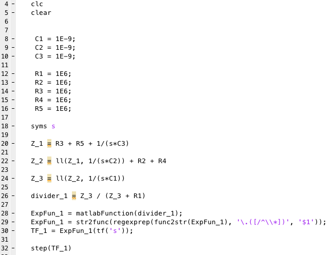
All I did in the MATLAB code above is find the total impedance and use voltage division to find the V_C1 voltage.
I made a function; 'll(x,y)' which returns x*y/(x+y). Kinda checky IMO.
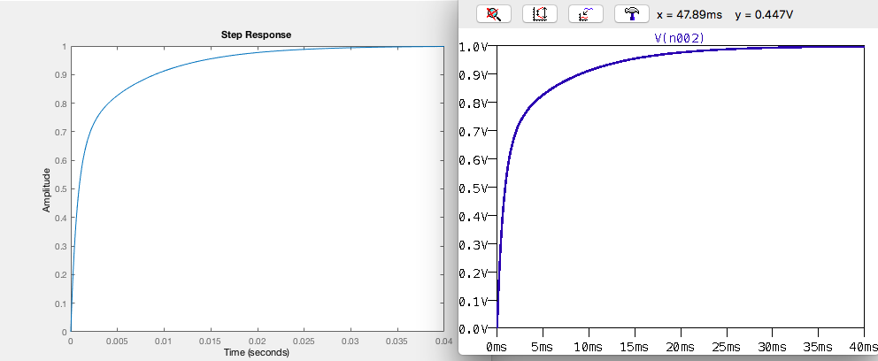
Below I compare the step response of my analytical answer with LTSpice Simulation. The left waveform is my MATLAB output for V_C1, the right waveform is my LTSpice output for V_C1 (I normalized the voltage to 1V). As far as I can tell they are identical.
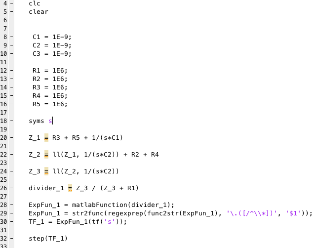
For fun, here's the transfer function. Oh how far it is from 1st order! I also have a case where C3 = 100nF which emphasizes the changing response.
symbolic to TF code: https://www.mathworks.com/matlabcentral/answers/310042-how-to-convert-symbolic-expressions-to-transfer-functions


