deleted 5 characters in body
Source Link
Jake quin
  • 2k
  • 3
  • 27
  • 52

I'm going to convert my DeWalt charger from 110V to 240V as I got sick of lugging a step converter around.

I have found two guides which use the exact model of charger I have but they have partly different solution. I would like to know more of what could be the reason that they did what they did.

It is clear that the transformer that powers the charging circuit can handle 240V. Both of the guides replaced the 200V 220uF which I totally understand - that capacitor would pop under 240 VAC and should be replaced with a value above the peak 400V + should be fine.

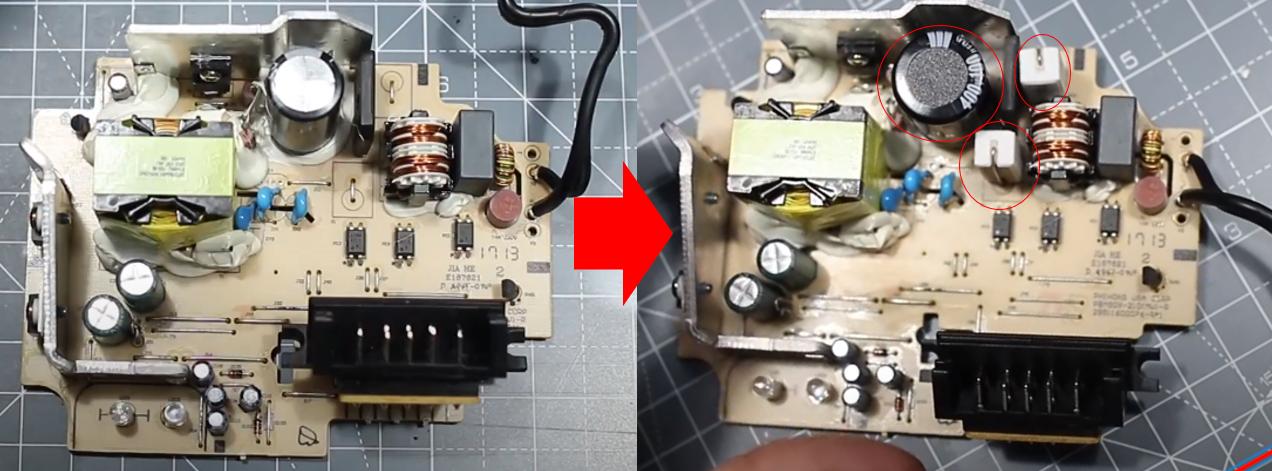
Now the similarities end, the first guide changed the capacitor and added 2 0.33Ohm 5W resistors.

enter image description here

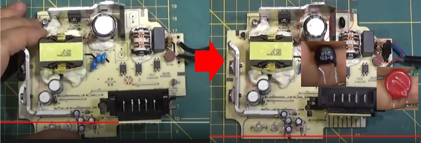
The second guide did not speak in english so I did not understand what he was saying but basically I think he add a varistor on the main input and instead of using a resistor I'm not sure what that black thing is (ceramic capacitor?) but why would he add a capacitor? If you look closely look on either of the videos you might notice that that slot is labeled "R" so I assume a resistor is supposed to be placed there (instead of a jumper.)

enter image description here

Can someone help explain to me what could they possibly be doing? Sadly I don't currently have my charger so I can't take more detailed pictures of the circuit. But maybe someone may have an idea based on past experience.
I'm going to convert my DeWalt charger from 110V to 240V as I got sick of lugging a step converter around.

I have found two guides which use the exact model of charger I have but they have partly different solution. I would like to know more of what could be the reason that they did what they did.

It is clear that the transformer that powers the charging circuit can handle 240V. Both of the guides replaced the 200V 220uF which I totally understand - that capacitor would pop under 240 VAC and should be replaced with a value above the peak 400V + should be fine.

Now the similarities end, the first guide changed the capacitor and added 2 0.33Ohm 5W resistors.

enter image description here

The second guide did not speak in english so I did not understand what he was saying but basically I think he add a varistor on the main input and instead of using a resistor I'm not sure what that black thing is (ceramic capacitor?) but why would he add a capacitor? If you closely look on either of the videos you might notice that that slot is labeled "R" so I assume a resistor is supposed to be placed there (instead of a jumper.)

enter image description here

Can someone help explain to me what could they possibly be doing? Sadly I don't currently have my charger so I can't take more detailed pictures of the circuit. But maybe someone may have an idea based on past experience.

added 2 characters in body; edited title
Source Link
JRE
  • 73.6k
  • 10
  • 112
  • 195

Converting a DeWalt charger from 110v110V to 220v220V, rational of component selection from the guide

ImI'm going to convert my DeWalt charger fom 110vfrom 110V to 240v240V as iI got sick of lugging a step converter around. Now i

I have found two guides which usesuse the exact model of charger iI have but they have partly different solution. I would like to know more of what could be the reason theythat they did what they did.

It is clear that the transformer thatsthat powers the charging circuit can handle 240v240V. Both of the guides replaced the 200v200V 220uF which isI totally i understand, - that capacitor would pop under 240 VAC and should be replaced with a value above the peak 400v400V + should be fine.

Now the similarities end, the First Guidefirst guide changed the capacitor and added 2 0.33Ohm 5W resistorresistors.

enter image description here

The second guide did not speak in english so iI did not understand what he was saying but basically iI think he add a varistor on the main input and instead of using a resistor imI'm not sure what that black thing is (ceramic capacitor?) but why would he add a capacitor? ifIf you look closely look on either of the videos you might notice that that slot is labeled "R" so iI assume a resistor is supposed to be placed there (instead of a jumper.)

enter image description here

Can someone help explain to me what could they be possibly be doing  ? Sadly i dontI don't currently have my charger so i cantI can't take more detailed pictures of the circuit. But maybe someone may have an idea based on past experience.

Converting a DeWalt charger from 110v to 220v, rational of component selection from the guide

Im going to convert my DeWalt charger fom 110v to 240v as i got sick of lugging a step converter around. Now i have found two guides which uses the exact model of charger i have but they have partly different solution. I would like to know more of what could be the reason they they did what they did.

It is clear that the transformer thats powers the charging circuit can handle 240v. Both of the guides replaced the 200v 220uF which is totally i understand, that capacitor would pop under 240 VAC and should be replaced with a value above the peak 400v + should be fine.

Now the similarities end, the First Guide changed the capacitor and added 2 0.33Ohm 5W resistor

enter image description here

The second guide did not speak in english so i did not understand what he was saying but basically i think he add a varistor on the main input and instead of using a resistor im not sure what that black thing is (ceramic capacitor?) but why would he add a capacitor? if you look closely look on either of the videos you might notice that that slot is labeled "R" so i assume a resistor is supposed to be placed there (instead of a jumper)

enter image description here

Can someone help explain to me what could they be possibly doing  ? Sadly i dont currently have my charger so i cant take more detailed pictures of the circuit. But maybe someone may have an idea based on past experience.

Converting a DeWalt charger from 110V to 220V, rational of component selection from the guide

I'm going to convert my DeWalt charger from 110V to 240V as I got sick of lugging a step converter around.

I have found two guides which use the exact model of charger I have but they have partly different solution. I would like to know more of what could be the reason that they did what they did.

It is clear that the transformer that powers the charging circuit can handle 240V. Both of the guides replaced the 200V 220uF which I totally understand - that capacitor would pop under 240 VAC and should be replaced with a value above the peak 400V + should be fine.

Now the similarities end, the first guide changed the capacitor and added 2 0.33Ohm 5W resistors.

enter image description here

The second guide did not speak in english so I did not understand what he was saying but basically I think he add a varistor on the main input and instead of using a resistor I'm not sure what that black thing is (ceramic capacitor?) but why would he add a capacitor? If you look closely look on either of the videos you might notice that that slot is labeled "R" so I assume a resistor is supposed to be placed there (instead of a jumper.)

enter image description here

Can someone help explain to me what could they possibly be doing? Sadly I don't currently have my charger so I can't take more detailed pictures of the circuit. But maybe someone may have an idea based on past experience.

Source Link
Jake quin
  • 2k
  • 3
  • 27
  • 52

Converting a DeWalt charger from 110v to 220v, rational of component selection from the guide

Im going to convert my DeWalt charger fom 110v to 240v as i got sick of lugging a step converter around. Now i have found two guides which uses the exact model of charger i have but they have partly different solution. I would like to know more of what could be the reason they they did what they did.

It is clear that the transformer thats powers the charging circuit can handle 240v. Both of the guides replaced the 200v 220uF which is totally i understand, that capacitor would pop under 240 VAC and should be replaced with a value above the peak 400v + should be fine.

Now the similarities end, the First Guide changed the capacitor and added 2 0.33Ohm 5W resistor

enter image description here

The second guide did not speak in english so i did not understand what he was saying but basically i think he add a varistor on the main input and instead of using a resistor im not sure what that black thing is (ceramic capacitor?) but why would he add a capacitor? if you look closely look on either of the videos you might notice that that slot is labeled "R" so i assume a resistor is supposed to be placed there (instead of a jumper)

enter image description here

Can someone help explain to me what could they be possibly doing ? Sadly i dont currently have my charger so i cant take more detailed pictures of the circuit. But maybe someone may have an idea based on past experience.